Movable edge data shelter
An edge data and mobile technology, applied in the direction of construction, industrial buildings, small buildings, etc., can solve the problems of inconvenient disassembly and installation, inconvenient post-transportation, etc.
- Summary
- Abstract
- Description
- Claims
- Application Information
AI Technical Summary
Problems solved by technology
Method used
Image
Examples
Embodiment 1
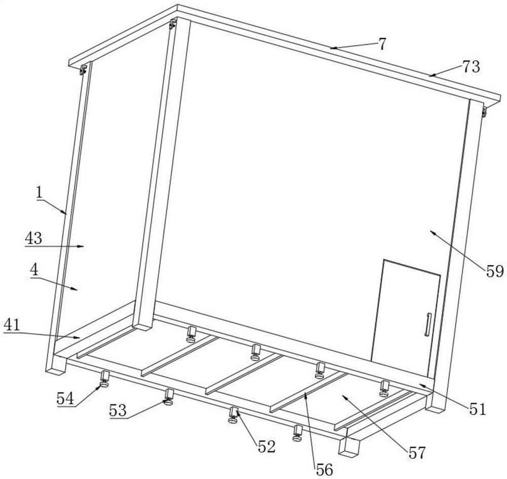
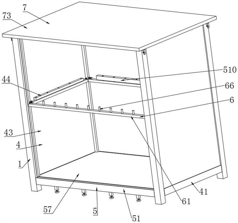
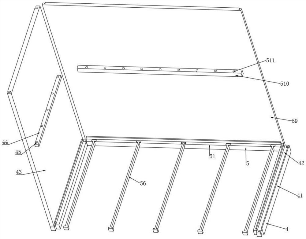
[0030] A mobile edge data shelter, comprising a column 1, a first L-shaped groove 2 and a second L-shaped groove 3 are respectively provided on the adjacent two sides of the outer surface of the column 1, and the inner cavity of the first L-shaped groove 2 is installed with a A transverse device 4, a longitudinal device 5 is installed in the inner cavity of the second L-shaped groove 3, a reinforcement device 6 is installed in the middle of the adjacent two sides of the outer surface of the column 1, and a capping device 7 is installed on the upper end surface of the column 1; 41. The first limiting slot 42, the horizontal plate 43, the first reinforcing plate 44 and the first reinforcing hole 45 are formed. The inner cavity of the first L-shaped groove 2 is slidably connected with a horizontal bar 41, and the upper end surface of the horizontal bar 41 is provided with a first Limiting slot 42, a transverse plate 43 is installed in the inner cavity of the first limiting groove ...
Embodiment 2
[0031] Embodiment 2: The difference between this embodiment and Embodiment 1 is that the longitudinal device 5 consists of a longitudinal rod 51, a rectangular block 52, a supporting threaded rod 53, a supporting pad 54, a T-shaped groove 55, an I-shaped rod 56, a bottom plate 57, The second limiting groove 58, the vertical plate 59, the second reinforcing plate 510 and the second reinforcing hole 511 are formed. The inner cavity of the second L-shaped groove 3 is slidably connected with the vertical rod 51, and the lower end surface of the vertical rod 51 is fixedly connected with a rectangular block. 52. The inner cavity of the rectangular block 52 is threadedly connected with a supporting threaded rod 53, and the lower end surface of the supporting threaded rod 53 is rotatably connected with a supporting pad 54; one end of the upper end surface of the longitudinal rod 51 is provided with a T-shaped groove 55, and the inner cavity of the T-shaped groove 55 is slidably connecte...
Embodiment 3
[0032] Embodiment 3: The difference between this embodiment and Embodiment 1 is that the reinforcing device 6 is composed of a reinforcing rod 61, a square sheet 62, an insertion rod 63, an insertion cap 64, an insertion spring 65 and a cylindrical nail 66, and the outer surface of the column 1 is composed of Reinforcing rods 61 are respectively installed on both sides of the rod, and two ends of the upper end surface of the reinforcing rod 61 are respectively fixedly connected with square sheets 62; On one side of the plug cap 64 and between the square-shaped pieces 62, a plug spring 65 is fixedly connected, and the upper end surface of the reinforcing rod 61 is fixedly connected with cylindrical nails 66 at equal intervals; A rectangular rod 74, an L-shaped insertion rod 75 and a return spring 76 are formed. The upper end surface of the column 1 is provided with a positioning hole 71. The positioning hole 71 is slidably connected with a positioning nail 72, and the upper end ...
PUM
 Abstract
Description
Claims
Application Information
 - R&D
- Intellectual Property
- Life Sciences
- Materials
- Tech Scout
- Unparalleled Data Quality
- Higher Quality Content
- 60% Fewer Hallucinations
Browse by: Latest US Patents, China's latest patents, Technical Efficacy Thesaurus, Application Domain, Technology Topic, Popular Technical Reports.
© 2025 PatSnap. All rights reserved.Legal|Privacy policy|Modern Slavery Act Transparency Statement|Sitemap|About US| Contact US: help@patsnap.com


