
Pneumatic motor servo system and control method

A technology of air motor and servo system, which is applied in fluid pressure actuation system components, fluid pressure actuation system testing, servo motor components, etc., and can solve problems such as difficulty in reaching the speed of the air motor, affecting the output speed of the air motor, and multiple losses , to achieve the effect of eliminating the loss

Pending Publication Date: 2022-07-29
CHINA NORTH VEHICLE RES INST
View PDF0 Cites 0 Cited by
  • Summary
  • Abstract
  • Description
  • Claims
  • Application Information

AI Technical Summary

Problems solved by technology

[0003] However, the output speed of the air motor is directly related to its air source. In the prior art, the air source has a lot of loss in the process of entering the air motor from the compressor, which directly affects the output speed of the air motor, making it difficult for the air motor to Reach or just get the required speed

Method used


Image

  • Pneumatic motor servo system and control method

Examples


Embodiment 1

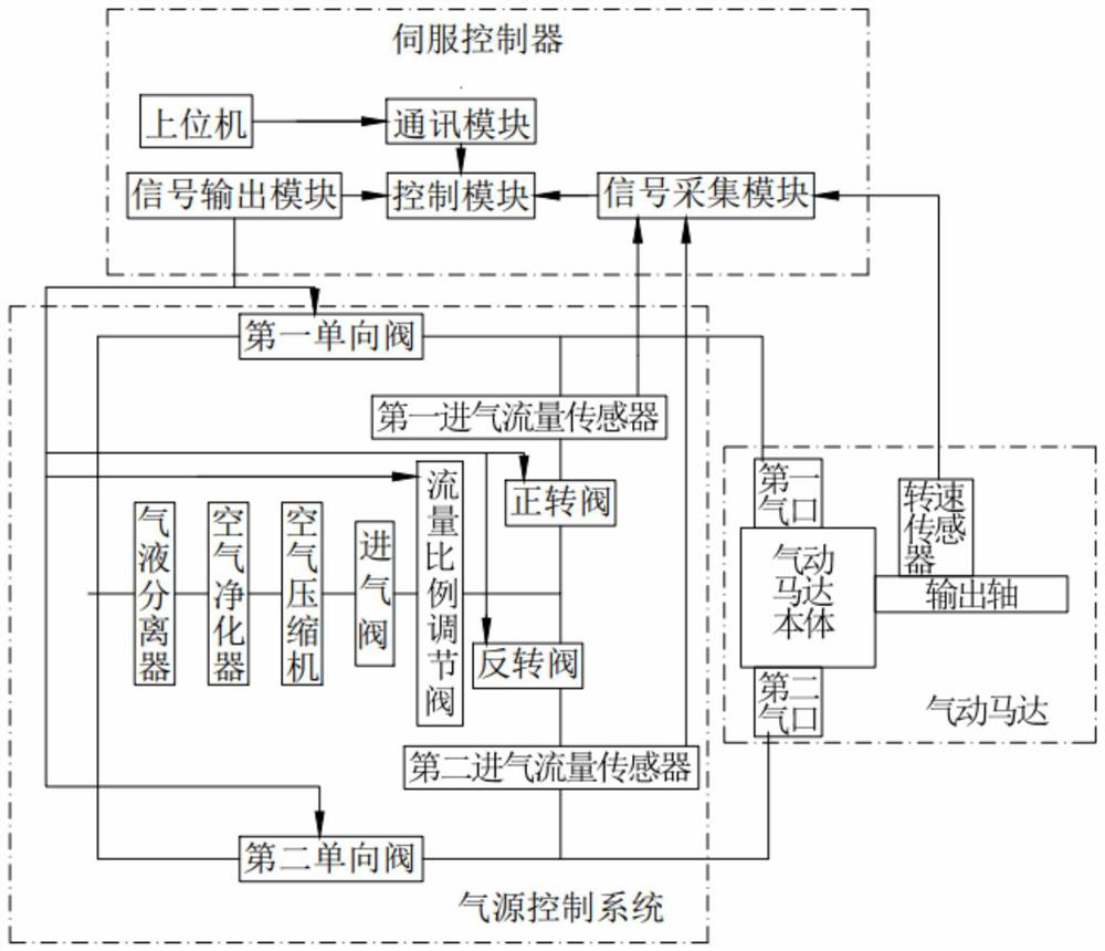
[0053] like figure 1 As shown, this embodiment provides a pneumatic motor servo system, including a pneumatic motor and an air source control system for supplying air to the pneumatic motor;

[0054] The air motor includes an air motor body, a first air port, a second air port and an output shaft; a rotational speed sensor is installed on the output shaft, and the rotational speed sensor acquires the rotational speed signal of the output shaft and transmits the rotational speed signal to the air source control system;

[0055] The air source control system is used to control the air source flow into the air motor body;

[0056] The air source control system includes: a gas-liquid separator, an air purifier, an air compressor, and an intake valve connected in sequence; the air source control system further includes a forward rotation valve, a reverse rotation valve, and a first intake air flow sensor and the second intake air flow sensor;

[0057] The first intake air flow se...


PUM


Abstract

The invention belongs to the technical field of pneumatic motors, and particularly relates to a pneumatic motor servo system and a control method.The pneumatic motor servo system comprises an air source control system, a pneumatic motor body, a first air port, a second air port and an output shaft; a rotating speed sensor is installed on the output shaft, and the air source control system controls the flow of an air source entering the pneumatic motor body. The air source control system comprises an air compressor, an air inlet valve, a forward rotation valve and a reverse rotation valve which are sequentially connected, the forward rotation valve and the reverse rotation valve are connected to the rear portion of the air inlet valve in parallel, the rear portion of the air inlet valve is further connected with a flow proportion adjusting valve, and the forward rotation valve and the reverse rotation valve are connected to the rear portion of the flow proportion adjusting valve in parallel. According to the pneumatic motor servo system, the output rotating speed of the pneumatic motor is obtained by arranging the rotating speed sensor on the output shaft, airflow entering the pneumatic motor is adjusted through the flow proportion adjusting valve, loss of an air source in the conveying process is eliminated or reduced, and the rotating speed needed by output of the pneumatic motor is ensured.

Description

technical field [0001] The invention belongs to the technical field of pneumatic motors, and in particular relates to a pneumatic motor servo system and a control method. Background technique [0002] Compared with traditional electric motors and hydraulic motors, air motors are lighter in weight and easy to install and transport; and because their working medium is compressed air, they will not cause fire; when the air motor is overloaded, it can keep balance with the air supply pressure and automatically stop. ; Compared with hydraulic motors, the leakage of compressed air will not pollute the environment; compared with electric motors, there is no motor damage caused by problems such as overvoltage, overcurrent, and insulation reduction. [0003] However, the output speed of the air motor is directly related to its air source. In the prior art, the air source has a lot of loss in the process of entering the air motor from the compressor, which directly affects the output ...

Claims


Application Information

Patent Timeline
IPC IPC(8): F15B21/08F15B21/048F15B13/02F15B13/16F15B19/00
CPCF15B21/087F15B21/048F15B13/02F15B13/027F15B13/16F15B19/005
Inventor 刘焱吕志鸿夏焕文王磊杨丽玲薛松
Owner CHINA NORTH VEHICLE RES INST
Learn More