Touch screen type flowmeter

A flowmeter and touch screen technology, applied in the field of flowmeters, can solve problems such as inconvenient for users to consult, unintelligent and convenient to use, single flowmeter settings, etc., and achieve the effects of convenient intelligent touch, convenient disinfection, convenient disassembly and assembly

Pending Publication Date: 2022-07-29
湖北亿立能科技股份有限公司
View PDF0 Cites 0 Cited by
  • Summary
  • Abstract
  • Description
  • Claims
  • Application Information

AI Technical Summary

Problems solved by technology

[0004] The purpose of the present invention is to provide a touch-screen flowmeter to solve the problem that the flowmeter in the prior art proposed in the above-mentioned background technology has relatively simple

Method used


Image

  • Touch screen type flowmeter
  • Touch screen type flowmeter
  • Touch screen type flowmeter

Examples


specific Embodiment approach 1

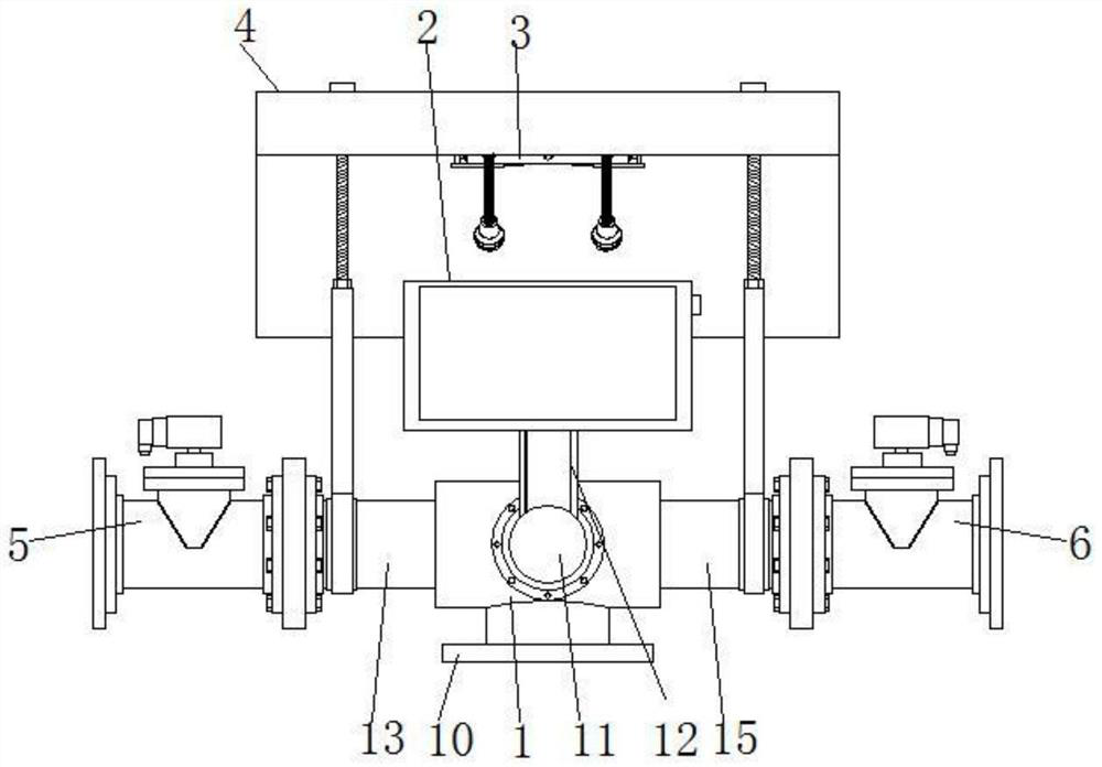
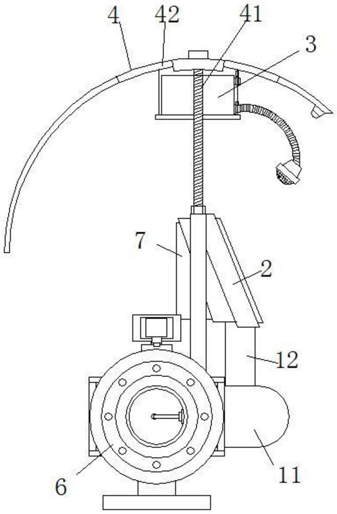
[0032] For the first specific implementation, please refer to Figure 1-8 , the present invention provides a technical solution: a touch screen flowmeter, comprising a valve body 1, a flowmeter touch screen 2, a disinfection structure 3, a protective structure 4, a left connecting pipe 5, a right connecting pipe 6 and a heat dissipation structure 7, A flow meter touch screen 2 is installed in the middle of the valve body 1 , and a left pipe head 13 is provided on the left side of the valve body 1 , and a left connecting pipe 5 is connected to the outer end of the left pipe head 13 , and the right side of the valve body 1 is provided with The right pipe head 15, and the right connecting pipe 6 is connected to the outer end of the right pipe head 15, and the left connecting pipe 5 and the right connecting pipe 6 are arranged symmetrically about the center line of the valve body 1; the left pipe head 13 on the valve body 1 A protective structure 4 is installed between it and the ...

specific Embodiment approach 2

[0034]Embodiment 2, this embodiment is a further limitation of Embodiment 1. In the present invention, the left and right parts of the valve body 1 are respectively provided with a left pipe head 13 and a right pipe head 15, and the left pipe head 13 and the right pipe head The pipe head 15 is a left-right symmetrical structure with respect to the center line of the valve body 1, and the two are connected and arranged. At the same time, a relatively long nozzle structure is provided on both sides of the valve body 1, mainly for the convenience of installing the left connecting pipe 5. The right connecting pipe 6 and the left connecting pipe 5 and the right connecting pipe 6 can be used to connect the outer pipes on both sides to avoid the direct connection of the left pipe head 13 and the right pipe head 15 to the pipes, so as to facilitate the separate disassembly and maintenance of the valve body 1 .

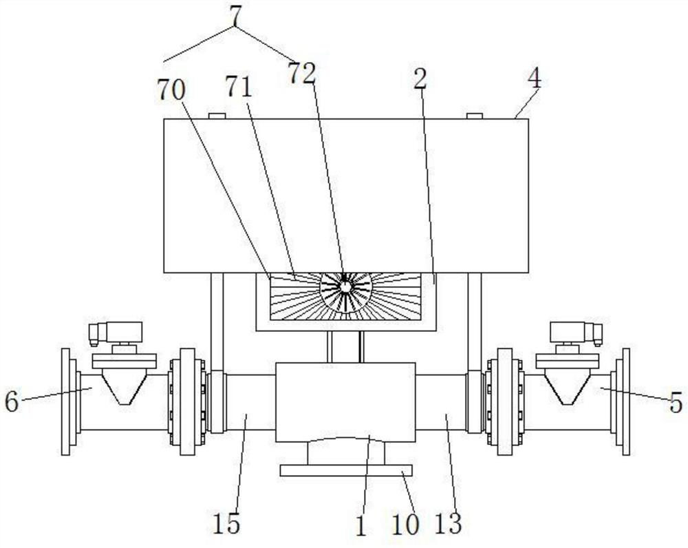
[0035] In the embodiment, a long-distance wireless data transmission modul...

specific Embodiment approach 3

[0036] Embodiment 3, this embodiment is a further limitation of Embodiment 1. The flow meter control mode in the present invention is set to touch screen control, which is convenient for intelligent touch control, and the detected data can be transmitted through the long-distance wireless data transmission module. The medium flow data is transmitted to the monitoring center, and the monitoring center can also remotely control the flowmeter through the long-distance wireless data transmission module, making the setting more intelligent and convenient.

[0037] In the embodiment, the sterilizing structure 3 is provided with a sterilizing water tank 30, the middle of the front side of the sterilizing water tank 30 is provided with a water inlet pipe port 31 and a drain pipe port 32, and an electromagnetic control valve is installed on the water inlet pipe port 31 and the drain pipe port 32. , and the left and right parts of the front side of the disinfection structure 3 are connec...


PUM


Abstract

The invention discloses a touch screen type flowmeter which comprises a valve body, a flowmeter touch screen, a disinfection structure, a protection structure, a left connecting pipeline, a right connecting pipeline and a heat dissipation structure, the flowmeter touch screen is installed in the middle of the valve body, a left pipe head is arranged on the left side of the valve body, and the outer end of the left pipe head is connected with the left connecting pipeline; a right pipe head is arranged on the right side of the valve body, and the outer end of the right pipe head is connected with a right connecting pipeline. A protection structure is installed between the left pipe head and the right pipe head on the valve body and covers the flowmeter touch screen, a disinfection structure is installed on the inner top of the protection structure, and meanwhile a heat dissipation structure is installed on the rear side face of the flowmeter touch screen. The touch screen type flow meter is reasonable in structural arrangement, abandons a traditional meter head type structure, adopts a touch screen type structure, can better meet the use requirements of people nowadays, is more intelligent and convenient, enables more data detected by the flow meter to be looked over and looked up, and is more intelligent and convenient to set.

Description

technical field [0001] The invention relates to the technical field of flowmeters, in particular to a touch screen type flowmeter. Background technique [0002] In the industrial or civil field, air, water, gas and various gases need to be measured. These fluids are closely related to people's daily life and social activities; mass flow meters are used to accurately measure the mass flow of gases. It has important applications in scientific research and production in various fields such as semiconductor and integrated circuit industry, special material discipline, chemical industry, petroleum industry, medicine, environmental protection and vacuum. [0003] However, the flowmeter in the prior art is relatively simple in settings, and the current flow status of the medium in the pipeline can only be seen from the meter head, which is inconvenient for users to independently consult more information, and is not intelligent and convenient to use. SUMMARY OF THE INVENTION [0...

Claims


Application Information

Patent Timeline
IPC IPC(8): G01F15/00G01F15/14G01F15/18H04N7/18
CPCG01F15/00G01F15/005G01F15/14G01F15/18G01F15/185H04N7/183
Inventor 张新强刘华堂张普王志强龚华斌熊涛周静
Owner 湖北亿立能科技股份有限公司
Why Eureka
Try Eureka