Optical lens for long-distance shooting
An optical lens and long-distance technology, applied in the field of optical lenses for long-distance shooting, can solve the problems of small field of view and poor imaging quality, and achieve the effects of large field of view, corrected aberrations, and good imaging quality
- Summary
- Abstract
- Description
- Claims
- Application Information
AI Technical Summary
Problems solved by technology
Method used
Image

Examples
Embodiment 1
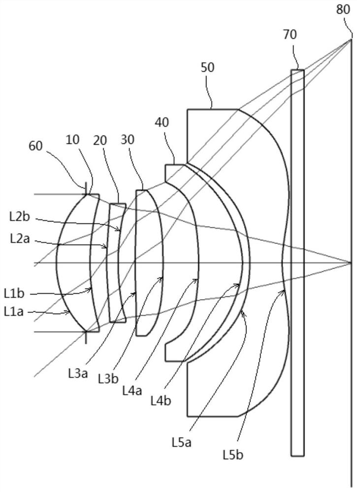
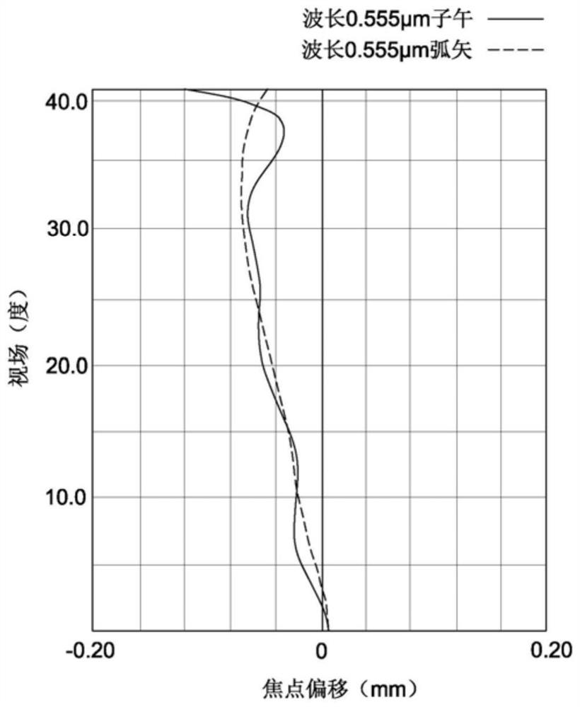
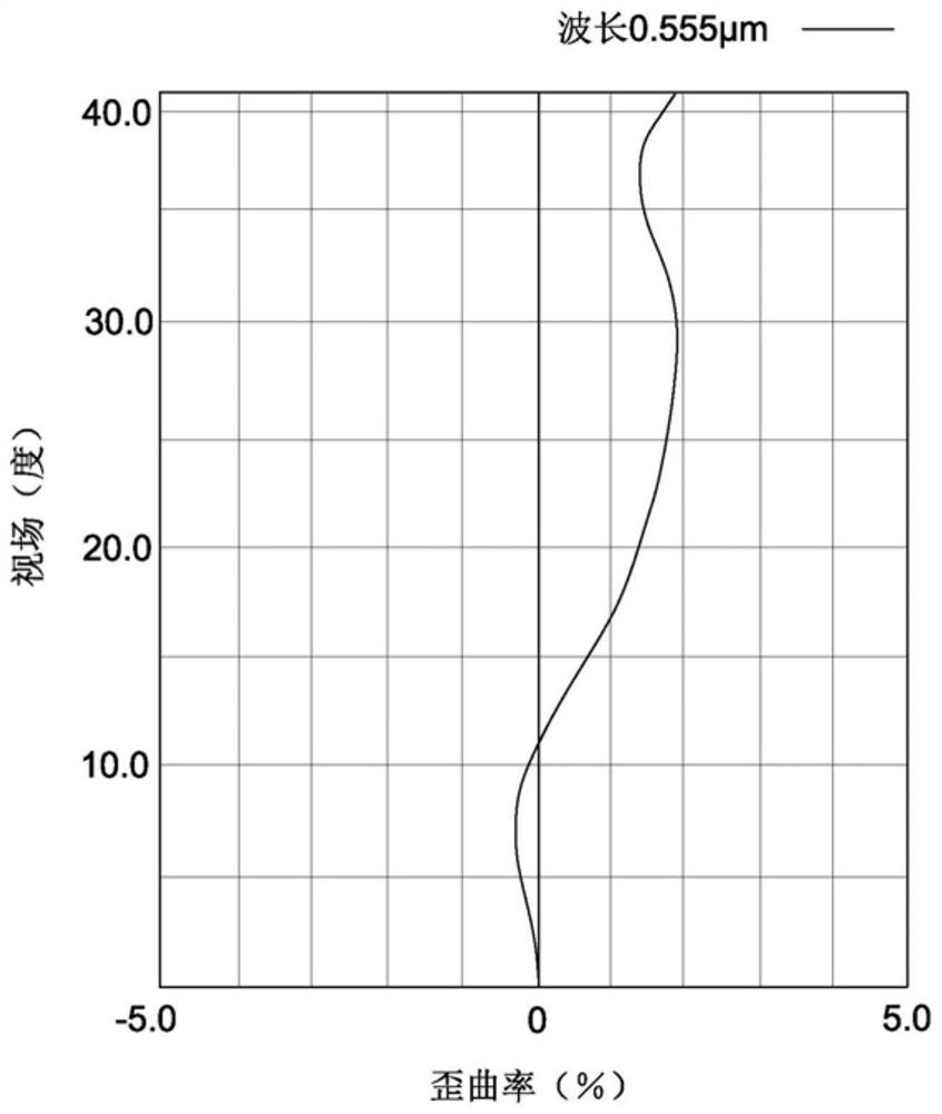
[0042] figure 1 It is a schematic structural diagram of the optical lens according to Embodiment 1 of the present invention. figure 2 It is the field curve (Field Curve) aberration diagram of the optical lens of the present invention. image 3 Distortion aberration diagram of the optical lens of the present invention. Figure 4 It is the longitudinal spherical aberration diagram (Longitudinal Spherical Aberration) of the optical lens of the present invention.
[0043] like figure 1 As shown, an optical lens for long-distance shooting in Embodiment 1, from the object side to the image side, sequentially includes:
[0044] Aperture 60;
[0045] The first lens 10 with positive refractive power, the object side near the optical axis of the first lens 10 is a convex surface, and the image side near the optical axis of the first lens 10 is a concave surface;
[0046] The second lens 20 with negative refractive power, the object side near optical axis of the second lens 20 is a...
Embodiment 2
[0070] Figure 5 It is a schematic structural diagram of the optical lens according to the second embodiment of the present invention. Image 6 It is a field curve (Field Curve) aberration diagram of the optical lens according to the second embodiment of the present invention. Figure 7 It is the distortion aberration diagram of the optical lens according to the second embodiment of the present invention. Figure 8 It is the longitudinal spherical aberration diagram (Longitudinal Spherical Aberration) of the optical lens of Example 2 of the present invention.
[0071] like Figure 5 As shown, an optical lens for long-distance shooting in Embodiment 1, from the object side to the image side, sequentially includes:
[0072] Aperture 60;
[0073] The first lens 10 with positive refractive power, the object side near the optical axis of the first lens 10 is a convex surface, and the image side near the optical axis of the first lens 10 is a concave surface;
[0074] The secon...
Embodiment 3
[0098] Figure 9 It is a schematic structural diagram of the optical lens according to Embodiment 3 of the present invention. Figure 10 It is a field curve (Field Curve) aberration diagram of the optical lens according to the third embodiment of the present invention. Figure 11 It is the distortion aberration diagram of the optical lens according to the third embodiment of the present invention. Figure 12 It is the longitudinal spherical aberration diagram (Longitudinal Spherical Aberration) of the optical lens of Example 3 of the present invention.
[0099] like Figure 9 As shown, an optical lens for long-distance shooting in Embodiment 3, from the object side to the image side, sequentially includes:
[0100] Aperture 60;
[0101] The first lens 10 with positive refractive power, the object side near the optical axis of the first lens 10 is a convex surface, and the image side near the optical axis of the first lens 10 is a concave surface;
[0102] The second lens ...
PUM
 Abstract
Description
Claims
Application Information
 - Generate Ideas
- Intellectual Property
- Life Sciences
- Materials
- Tech Scout
- Unparalleled Data Quality
- Higher Quality Content
- 60% Fewer Hallucinations
Browse by: Latest US Patents, China's latest patents, Technical Efficacy Thesaurus, Application Domain, Technology Topic, Popular Technical Reports.
© 2025 PatSnap. All rights reserved.Legal|Privacy policy|Modern Slavery Act Transparency Statement|Sitemap|About US| Contact US: help@patsnap.com