Annular combustion chamber model with integrated head structure and assembly method

An annular combustion chamber and combustion chamber technology, applied in teaching models, connecting components, instruments, etc., can solve the problems of inability to take into account the fine structure and low cost, the complex structure of the aero-engine combustion chamber, and the difficulty of taking into account the fineness of the structure, etc. Convenient assembly design, good teaching display value, and the effect of manufacturing

Active Publication Date: 2022-07-29
NORTHWESTERN POLYTECHNICAL UNIV
View PDF12 Cites 0 Cited by
  • Summary
  • Abstract
  • Description
  • Claims
  • Application Information

AI Technical Summary

Problems solved by technology

[0002]Due to the complexity of the structure of the aero-engine combustion chamber, the existing solid model of aero-engine cannot balance fine structure and low cost
It is difficult to control the cost of the existing solid models of various aero-engine combustion chambers when the structure is refined, and it is often difficult to disassemble and assemble without special tools; Display of results

Method used


Image

  • Annular combustion chamber model with integrated head structure and assembly method
  • Annular combustion chamber model with integrated head structure and assembly method
  • Annular combustion chamber model with integrated head structure and assembly method

Examples


Embodiment 1

[0046]This embodiment is an annular combustion chamber model with an integrated head structure, which achieves a high-precision restoration of the typical structure of the annular combustion chamber of a modern engine. The parts involved in this embodiment can be processed and have sufficient strength under the conditions of applying the photo-curing 3D printing process. The annular combustion chamber model with an integrated head structure described in this embodiment can be combined with other parts models, including a high-pressure compressor model, a high-pressure turbine model, and a low-pressure turbine model.

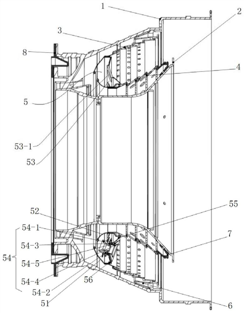
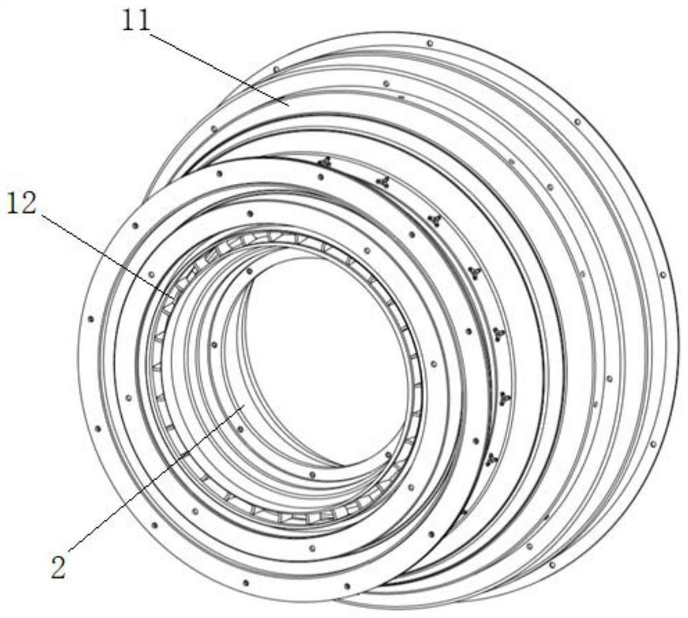
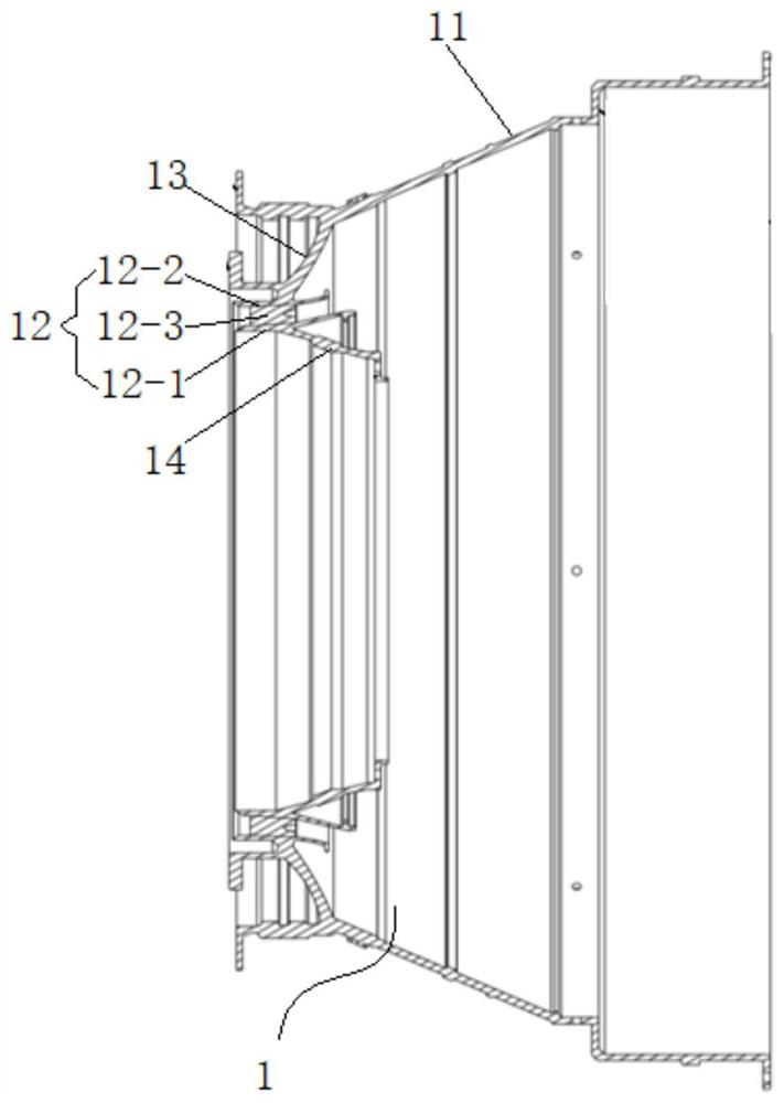
[0047] like Figure 1 to Figure 9 As shown, this embodiment provides an annular combustion chamber model with an integrated head structure, including an outdoor casing 1, an indoor casing 2, an outer casing 3 of a flame tube, an inner casing of the flame tube 4 and a flame tube head 5 ;

[0048] The combustion outdoor casing 1 includes a combustion outdoor casi...

Embodiment 2

[0067] The present embodiment provides a method for assembling an annular combustion chamber model with an integrated head structure, including the following steps:

[0068] Step 1, connect and fix the flame tube head, then connect the flame tube head with the flame tube outer shell and the flame tube inner shell respectively to form the flame tube as a whole;

[0069] Step 2, connect and fix the inner support ring with the casing in the combustion chamber, and connect the rear end of the casing in the combustion chamber to the turbine inlet guide of the high-pressure turbine model;

[0070] Step 3, install the combustion outdoor casing, and the combustion outdoor casing is connected to the combustion indoor casing, the outer support ring, and the high-pressure turbine model in sequence;

[0071] In step 4, the sealing ring is connected with the casing outside the combustion chamber, and the connection between the combustion chamber and the high-pressure compressor model is re...


PUM


Abstract

The invention discloses an annular combustion chamber model with an integrated head structure and an assembly method. The combustion chamber model comprises a combustion chamber outer casing, a combustion chamber inner casing, a flame tube outer casing, a flame tube inner casing and a flame tube head. The structural characteristics of engine parts are obvious, and low-cost split printing and combined structures of the flame tube head are achieved on the premise that the requirement for high fineness is met; production and manufacturing are achieved, meanwhile, specific structural features are reserved, the assembly difficulty of a user is simplified, and the problems that a traditional low-cost aero-engine combustion chamber model is too few in details, cannot meet teaching requirements, is too small in size and is difficult to display are solved.

Description

technical field [0001] The invention belongs to the technical field of aero-engines, and in particular relates to an annular combustion chamber model with an integrated head structure and an assembling method. Background technique [0002] Due to the complexity of the aero-engine combustion chamber structure, the existing aero-engine solid model cannot take into account the fine structure and low cost. Existing solid models of various types of aero-engine combustion chambers are difficult to control the cost when the structure is refined, and are often not easy to disassemble and assemble without special tools; under the requirement of low cost, it is difficult to take into account the fineness of the structure, thus losing the due model of the model. Display of results. SUMMARY OF THE INVENTION [0003] In view of the deficiencies of the prior art, the purpose of the present invention is to provide an annular combustion chamber model with an integrated head structure and...

Claims


Application Information

Patent Timeline
IPC IPC(8): G09B25/02B29C65/56F16B13/10
CPCG09B25/02B29C65/562F16B13/10Y02T50/60
Inventor 高文君田恩宇乔亚斐路培强张贤王承熙徐永康龚翔宇付爽袁菁涛吕明桦
Owner NORTHWESTERN POLYTECHNICAL UNIV
Why Eureka
Try Eureka