Box-type substation
A box-type substation and substation technology, applied in the field of substations, can solve the problems of leakage, infiltration, electric shock and other problems in substations, and achieve the effect of improving efficiency
Pending Publication Date: 2022-07-29
陈浩
1 Cites 1 Cited by
AI-Extracted Technical Summary
Problems solved by technology
[0004] The above-mentioned related technical solutions have the following defects: when the urban flood water level rises higher than the bottom of the substation, the...
Abstract
The invention relates to a box-type substation which comprises a substation body, a base, an inflation device and an inflatable air bag, the substation body is arranged on the top surface of the base, the air bag is located between the base and the substation body, the inflation device is used for inflating the air bag, and only the part, located around the substation body, of the air bag can be inflated. When the air bag is not inflated with air, the air bag is flatly laid on the top face of the base, the projection of the air bag on the transformer substation body completely covers the transformer substation body, and after the air bag is inflated with the air through the air inflation device, the part, located around the transformer substation body, of the air bag expands and is tightly attached to the bottom end of the transformer substation body. When the water level rises due to waterlogging in a city, the inflation device inflates the air bag in time, and the inflated air bag can be tightly attached to the bottom end of the transformer substation body, so that the transformer substation body is protected, and the probability of electric leakage of the transformer substation during waterlogging can be reduced.
Application Domain
Substation/switching arrangement casingsDistribution substations
Technology Topic
Power substationTransformer +1
Image
Examples
- Experimental program(1)
Example Embodiment
[0042] Attached to the following Figure 1-11 This application will be described in further detail.
[0043] The embodiments of the present application disclose a box-type substation.
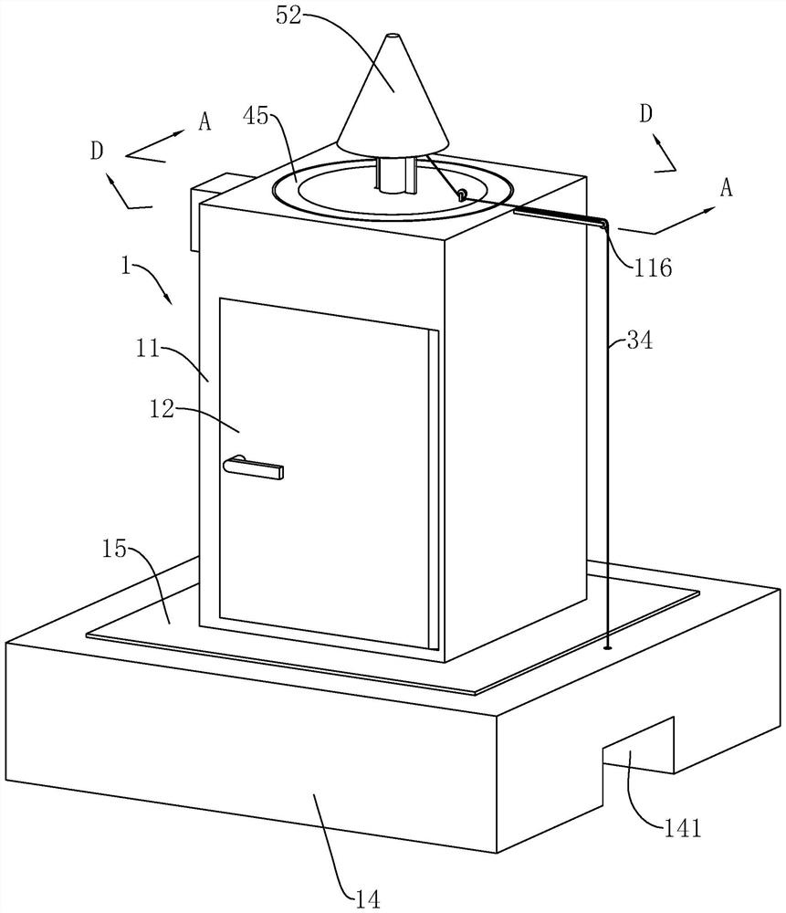
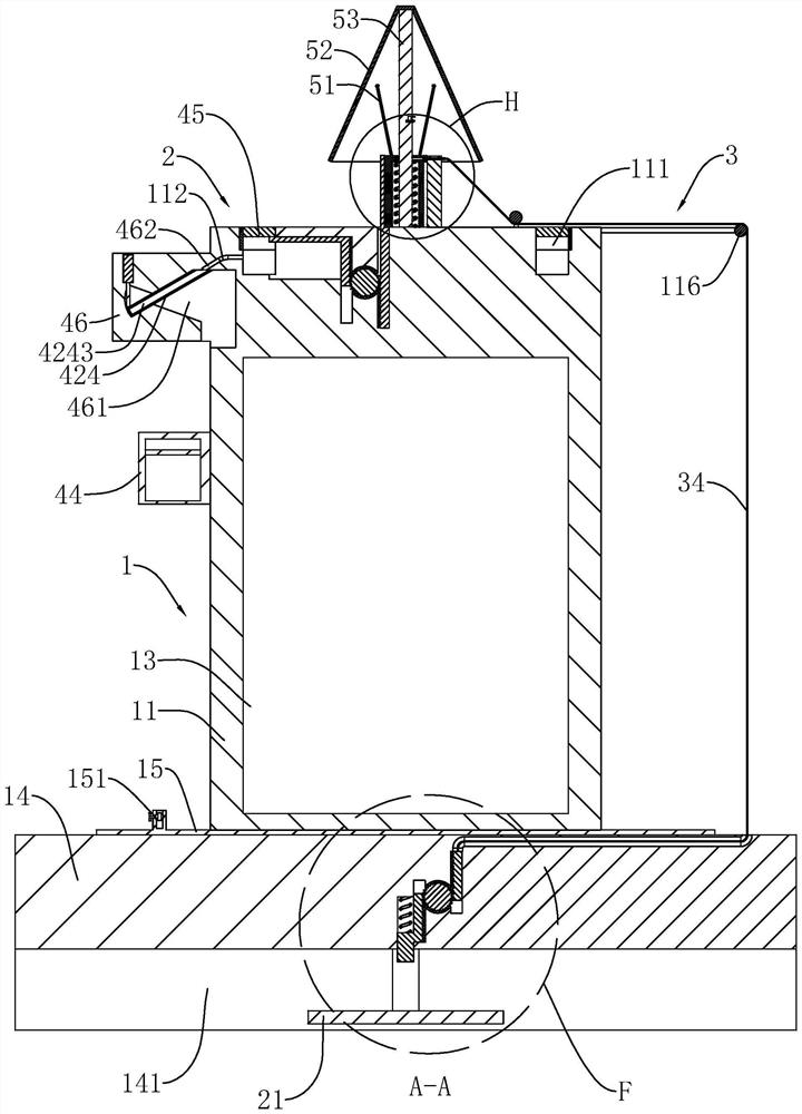
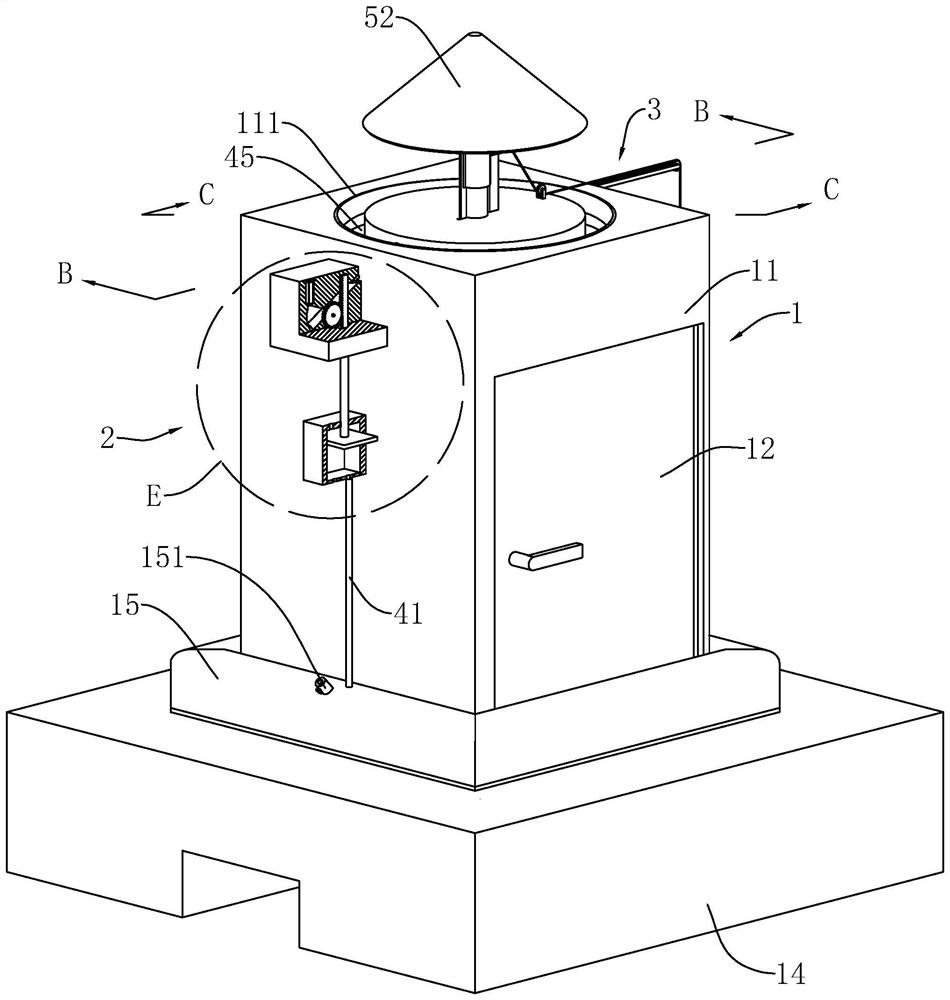
[0044] refer to figure 1 , figure 2 , a box-type substation in this embodiment includes a substation body 1 , a base 14 , an inflation device 2 and an inflatable air bag 15 . The substation body 1 includes a box body 11 with an accommodating cavity 13 and a door panel 12 hinged on the box body 11. The accommodating cavity 13 is used for placing various equipment such as transformers. When the airbag 15 is not filled with gas, the airbag 15 is laid flat on the top surface of the base 14 , the airbag 15 is located between the base 14 and the box body 11 , the box body 11 is fixed on the base 14 by the airbag 15 , and the airbag 15 is on the box body 11 . The projection on the box body 11 is completely covered, and only the part of the airbag 15 around the substation body 1 can be inflated. refer to figure 1 , image 3 , the inflator 2 is used to inflate the airbag 15, when the inflator 2 fills the airbag 15 with gas, the part of the airbag 15 around the substation body 1 expands and closely fits the bottom end of the substation body 1. An exhaust valve 151 is installed on the airbag 15 . When the exhaust valve 151 is opened, the gas in the airbag 15 is discharged through the exhaust valve 151 .
[0045] refer to figure 1 , image 3 , When the water level of urban flood disaster rises, the base 14 can provide buffer time due to its certain height, so that the inflator 2 can inflate the airbag 15 in time, and the inflated airbag 15 can be closely attached to the bottom end of the substation body 1, and can also provide the door panel. 12. Applying force to make the door panel 12 close better, reducing the probability of water infiltrating into the accommodating cavity 13 from the gap between the door panel 12 and the box 11, thereby protecting the substation body 1 and reducing the occurrence of waterlogging The probability of leakage in the substation.
[0046] refer to figure 2 , image 3 , the inflatable device 2 includes a floating plate 21, a starting device 3 and an air pumping device 4, a water inlet channel 141 is provided on the bottom surface of the base 14, and the length direction of the water inlet channel 141 is arranged horizontally and both ends are communicated with the outside world, the floating plate 21 is slidably connected to the water inlet channel 141 along the vertical direction, and the floating plate 21 can float on the water surface. The operator presets the height of the warning water level. When the floating plate 21 moves to the height of the warning water level, the starting device 3 drives the inflating device 4 to start operation, and the inflating device 4 is used to inflate the airbag 15 .
[0047] refer to image 3 , Figure 4 , the pumping device 4 includes an air delivery pipe 41, a driving member 42, a first one-way valve, a second one-way valve, a piston 43 and a pump 44 with an inner cavity 441, and the pump 44 is fixed on the outer wall of the box body 11, The piston 43 is slidably connected to the inner cavity 441 in the vertical direction and divides the inner cavity 441 into an upper cavity 4411 and a lower cavity 4412 which are not communicated with each other. sports. Both the upper cavity 4411 and the lower cavity 4412 are provided with through holes communicating with the outside world. The second one-way valve is arranged on the through holes of the lower cavity 4412 and only allows the outside air to enter the lower cavity 4412. 15 and the lower chamber 4412, the first one-way valve is arranged on the air delivery pipe 41 and only the air in the lower chamber 4412 enters the air bag 15 through the air delivery pipe 41. The driving member 42 continuously inflates the airbag 15 by driving the piston 43 to slide back and forth.
[0048] refer to image 3 , Figure 5 , the center of the top surface of the box body 11 is provided with an annular groove 111, the axial direction of the annular groove 111 is vertically arranged, the annular groove 111 is slidably connected in the vertical direction with an annular block 45, and the annular block 45 is arranged coaxially with the annular groove 111, The starting device 3 is used to drive the annular block 45 to slide on the annular groove 111. The inner wall of the annular groove 111 is provided with a first flow channel 112 that communicates with the outside world. The altitude position gradually decreases. When the top end of the annular block 45 moves above the first flow channel 112 , the annular block 45 blocks the first flow channel 112 . When the annular block 45 moves below the first flow channel 112 , the rainwater can flow into the first flow channel 112 through the annular groove 111 .
[0049] refer to Figure 4 , Figure 5 , the driving member 42 includes a first gear 421, a first rack 422, a rotating rod 423 and a straight cylinder 424, an extension block 46 is fixed on the outer wall of the box 11, and the extension block 46 is located just above the air cylinder 44. A movable slot 461 is defined in the extension block 46, and the bottom end of the movable slot 461 communicates with the outside world. The extension block 46 is also provided with a second flow channel 462 that communicates with the movable groove 461 and the first flow channel 112 . decline. The rotating rod 423 is rotatably connected in the movable groove 461, the axis direction of the rotating rod 423 is set horizontally, the straight cylinder 424 is fixed on the rotating rod 423, the length direction of the straight cylinder 424 is perpendicular to the axial direction of the rotating rod 423, and the two ends of the straight cylinder 424 are respectively Located on both sides of the rotating rod 423 . The parts of the straight cylinder 424 on both sides of the rotating rod 423 are the first end 4241 and the second end 4242 respectively. The rotation angle is limited, and the angle at which the straight cylinder 424 can rotate back and forth in the movable groove 461 is less than 60°. The end surface of the first end 4241 is provided with a water receiving groove 4243 , the depth direction of the water receiving groove 4243 is parallel to the length direction of the straight cylinder 424 , and the two ends of the water receiving groove 4243 are located on both sides of the rotating rod 423 respectively.
[0050] refer to Figure 4 , Figure 5 , when there is no water in the water receiving groove 4243, the second end 4242 is heavier than the first end 4241, the second end 4242 is rotated downward to abut on the inner bottom wall of the movable groove 461, and the first end 4241 is rotated upward to the second end Above the 4242 , the notch of the water receiving groove 4243 is disposed facing the second flow channel 462 , and the rainwater flowing out of the second flow channel 462 can flow into the water receiving groove 4243 . When the water in the sink 4243 is almost full, the first end 4241 is heavier than the second end 4242, the first end 4241 is rotated downward and the water in the sink 4243 is poured out. One end 4241 is turned back to the water receiving state.
[0051] refer to Figure 4 , the first gear 421 is coaxially and fixedly connected to the rotating rod 423, the first rack 422 is slidably connected to the extension block 46 in the vertical direction, the first rack 422 is meshed and connected to the first gear 421, and the first rack The bottom end of 422 protrudes from the extension block 46 and then extends into the air pump 44 and is fixed on the piston 43 .
[0052] refer to image 3 , Figure 5 , the starting device 3 is used to control the movement of the annular block 45 , which is equivalent to controlling the communication of the first flow channel 112 . Only in the event of waterlogging, the rainwater can enter the first flow channel 112 and the second flow channel 462 through the annular groove 111 . refer to image 3 , Figure 4 , the rainwater acts on the straight cylinder 424, the straight cylinder 424 moves through the lever principle, and the balance of both ends of the straight cylinder 424 is transferred by storing a certain amount of rainwater, so as to realize the back and forth rotation of the rotating rod 423, and then through the first gear 421 and the first rack 422 The cooperation of the piston 43 drives the piston 43 to slide back and forth, thereby realizing the inflation of the airbag 15 .
[0053] refer to image 3 , Figure 4, the airbag 15 is provided with an air pressure detector, a cylinder 463 is fixed in the extension block 46, and the output shaft of the cylinder 463 is vertically downward and facing the second end 4242 of the straight cylinder 424. When the air pressure value detected by the air pressure detector reaches When the air bag 15 is fully inflated, the rod of the piston 43 of the air cylinder 463 is extended, so that the straight cylinder 424 is always in a water-receiving state, the straight cylinder 424 does not rotate, and the inflator 2 does not inflate the air bag 15 any more.
[0054] refer to figure 2 , Image 6 , the starting device 3 includes a second rack 31, a third rack 32, a second gear 33, a first spring 313, a locking lever 341 and a pull rope 34, the second rack 31 and the third rack 32 are both vertically The second gear 33 is rotatably connected to the base 14 in the direction of the horizontal axis, and the second rack 31 and the third rack 32 are respectively located on both sides of the second gear 33 and are meshed with the second gear 33. 33 on. In order to prevent the second rack 31 from being separated from the base 14 during sliding, the second rack 31 includes a rack portion 311 and an abutting portion 312 . The rack portion 311 is fixed on one side of the abutting portion 312 , and the base 14 The first vertical slot 142 and the second vertical slot 143 are vertically arranged and communicated with each other. The bottom end of the first vertical slot 142 is communicated with the movable slot 461, and the second vertical slot 143 is located in the base 14 and is not communicated with the outside world. , the rack portion 311 is slidably connected to the second vertical slot 143 , and the abutting portion 312 is slidably connected to the first vertical slot 142 . The first spring 313 is disposed in the first vertical slot 142 , two ends of the first spring 313 abut on the top wall of the first vertical slot 142 and the abutting portion 312 respectively, and the first spring 313 is always in a compressed state. When no external force acts on the second rack 31, the rack portion 311 moves to abut against the bottom surface of the second vertical groove 143, and the bottom end of the abutting portion 312 extends into the movable groove 461 and is located below the warning water level , the bottom end of the contact portion 312 is located just above the floating plate 21 . One end of the pulling rope 34 is fixed on the third rack 32 , and the other end of the pulling rope 34 extends out of the base 14 and is fixed on the locking rod 341 .
[0055] refer to figure 1 , figure 2 In order to reduce the wear and tear of the pull rope 34 during the pulling process, a plurality of rollers 116 are rotatably connected to the path of the pull rope 34 on the box body 11 , and the pull rope 34 abuts and passes through the plurality of rollers 116 .
[0056] refer to Figure 5 , Figure 7 , the starting device 3 also includes a vertical rod 35, a fourth rack 361, a fifth rack 362, a third gear 363 and an elastic member 37. The elastic member 37 includes a fixed block 371, a moving block 372 and a second spring 373. The fixed block 371 is vertically fixed at the center position of the top surface of the box body 11, the bottom end of the moving block 372 is provided with a first groove 3721 matching the fixed block 371, and the moving block 372 is sleeved through the first groove 3721 and is slidably connected in the vertical direction. On the fixing block 371, the top of the fixing block 371 is provided with a second groove 3711 for accommodating the second spring 373, the first groove 3721 is always in communication with the second groove 3711, and the two ends of the second spring 373 are respectively abutted on the second groove 3711 on the bottom wall and on the top wall of the first groove 3721. The vertical rod 35 is vertically fixed on the top surface of the box body 11 and is located on one side of the elastic member 37, the locking rod 341 is slidably connected to the vertical rod 35 in the horizontal direction, and the outer wall of the fixing block 371 is provided with a hole for the locking rod 341 to be inserted into. Jack 3722.
[0057] refer to Figure 5 , Figure 7 , the fourth rack 361 and the fifth rack 362 are both slidably connected to the box body 11 in the vertical direction, the third gear 363 is rotatably connected to the box body 11, the axis direction of the third gear 363 is arranged horizontally, the fourth The rack 361 and the fifth rack 362 are located on two sides of the third gear 363 respectively and are meshedly connected to the third gear 363 . The top end of the fourth rack 361 is fixed on the bottom surface of the annular block 45 , and the top end of the fifth rack 362 extends out of the box 11 and is fixed on the moving block 372 .
[0058] refer to figure 2 , Figure 8 , when the floating plate 21 is below the warning water level, the locking rod 341 is inserted into the jack 3722, the fixing block 371 overcomes the elastic force of the second spring 373 and moves to abut on the top surface of the box body 11, at this time the annular block 45 is in the first Under the cooperation of the four racks 361 , the third gear 363 and the fifth rack 362 , the top end of the annular block 45 moves above the first flow channel 112 .
[0059] refer to figure 2 , Image 6 , when the floating plate 21 moves up to the warning water level, the floating plate 21 pushes the second rack 31 to move up, and the second rack 31 drives the third rack 32 to move down through the second gear 33. Refer to Figure 5 , Figure 7 , and then pull the pull rope 34 to drive the locking rod 341 out of the socket 3722, and then the fixing block 371 moves up under the action of the second spring 373 without the locking of the locking rod 341, thereby driving the fifth rack 362 to move up, the fifth The rack 362 moves up through the third gear 363 to drive the fourth rack 361 to move down, and finally the fourth rack 361 drives the ring block 45 to move down below the first flow channel 112 , so that rainwater can enter the first flow channel through the annular groove 111 112, start the pumping device 4 to work.
[0060] refer to Figure 5 , Figure 7 , the box body 11 is also provided with a water collecting device 5. The water collecting device 5 includes an umbrella rod 51, an umbrella surface 52 and a plurality of umbrella frames 53. The umbrella rod 51 is vertically fixed on the top surface of the box body 11. The top end passes through the fixed block 371 and the moving block 372 in sequence and is located above the moving block 372 , and the umbrella rod 51 does not affect the second spring 373 . The center of the bottom surface of the umbrella surface 52 is fixed on the top of the umbrella pole 51 , and the two ends of the umbrella stand 53 are hinged on the bottom surface of the umbrella surface 52 and the top surface of the fixing block 371 respectively. refer to figure 2 , Figure 8 , when the locking lever 341 is inserted into the jack 3722, the umbrella surface 52 is retracted; refer to Figure 5 , Figure 7 , when the locking rod 341 is away from the insertion hole 3722 , the umbrella surface 52 is opened and the water on the umbrella surface 52 can just flow into the annular groove 111 .
[0061] refer to Figure 5 , the rainwater hitting the umbrella surface 52 can gather and fall into the annular groove 111, and the umbrella surface 52 plays the role of collecting rainwater, which can make the water flow in the first flow channel 112 and the second flow channel 462 larger, so as to better The straight cylinder 424 is driven to rotate faster, which ultimately improves the efficiency of inflation.
[0062] refer to Figure 5 , Figure 7 , the umbrella rod 51 is provided with a locking piece 54 , when the umbrella surface 52 is opened, the locking piece 54 is used to lock the moving block 372 and the umbrella rod 51 together. refer to Figure 7 , Figure 8 , the locking member 54 includes a locking block 541, a connecting block 542, a pressing block 543 and a fourth spring 544, the umbrella rod 51 is provided with a hidden groove 531, and the two ends of the connecting block 542 are respectively vertically fixed on the locking block 541 and the pressing block 543, the locking block 541, the connecting block 542 and the pressing block 543 are slidably connected in the hidden groove 531 along the sliding direction parallel to the locking rod 341, the connecting block 542 is arranged vertically, and the two ends of the fourth spring 544 are respectively fixed in the hidden groove 531. On the locking block 541 and on the inner wall of the hidden groove 531 away from the outside world, when there is no external force, the connecting block 542 moves under the action of the fourth spring 544 to abut on the side wall of the hidden groove 531 close to the outside world, locking The ends of the block 541 and the pressing block 543 protrude from the outside, and the pressing block 543 is located above the locking block 541 . A second inclined surface 5411 is defined on the bottom surface of the locking block 541 .
[0063] Figure 5 , Figure 7 , the two ends of the socket 3722 pass through. When the umbrella surface 52 is opened, the moving block 372 moves up and pushes the locking block 541 to slide toward the hidden groove 531 side until the socket 3722 is facing the locking block 541. When the locking block 541 is in the first Under the elastic force of the four springs 544, the insertion hole 3722 is inserted, so as to realize the locking of the moving block 372 and the umbrella rod 51. At this time, the pressing block 543 is located above the moving block 372, and the operator can realize the moving block by pressing the pressing block 543. Unlock between 372 and umbrella pole 51.
[0064] refer to Figure 9 , Figure 10 , a sealing ring 113 is fixed on the circumferential inner wall of the top end of the annular groove 111 . A splash-proof water ring 114 is fixed below the sealing ring 113 , and the annular block 45 , the splash-proof water ring 114 and the sealing ring 113 are coaxially arranged. refer to figure 1 , Figure 11 , when the umbrella surface 52 is retracted, the top end of the annular block 45 moves to the top of the first flow channel 112 . refer to Figure 9 , Figure 10 The box body 11 is provided with a driving member 255. When the umbrella surface 52 is opened, the annular block 45 moves to the bottom of the first flow channel 112, and the driving member 255 drives the bottom end of the splash-proof water ring 114 toward the axis side of the annular groove 111. Moving, the inner wall of the water-splashing ring 114 is used to receive the rainwater that falls on the umbrella surface 52, and the water-splashing ring 114 is used to reduce the degree of splashing of the liquid that hits on it. The splash water ring 114 can be made of 4D air fiber or hard sponge.
[0065] refer to figure 1 , Figure 11 , when the top end of the annular block 45 moves above the first flow channel 112 , the sealing ring 113 is used to prevent rainwater from entering the annular groove 111 . refer to Figure 9 , Figure 10 , when the top end of the annular block 45 moves below the first flow channel 112 , the bottom end of the water-splashing ring 114 tapers toward the side of the axis, so that the inner wall of the water-splashing ring 114 is inclined and used to receive the umbrella surface 52 Compared with the rainwater falling directly on the annular groove 111 , the rainwater hitting the splash-proof water ring 114 can reduce the probability of rainwater splashing out of the annular groove 111 , thereby improving the rainwater collection effect.
[0066] refer to Figure 10 , Figure 11 The second driving member 55 includes a plurality of driving rods 551, a plurality of third springs 552 and a plurality of driving rods 553. The driving rods 553 are slidably connected to the box body 11 along the axis direction perpendicular to the annular groove 111, and the length of the driving rods 553 The direction is parallel to the sliding direction of the driving rod 553 . One end of the driving rod 553 extends into the annular groove 111 and is fixed on the outer wall of the water-splashing ring 114 . On the splash ring 114 , the extension line of the driving rod 553 in the longitudinal direction intersects with the axis of the annular groove 111 at one point. The box body 11 is opened with a plurality of limit slots 115. The plurality of limit slots 115 are not communicated with the annular groove 111 and surround the annular groove 111. The plurality of limit slots 115 correspond to the plurality of driving rods 553, which drive A limiting block 5531 is fixed on the bottom surface of the rod 553 , and the limiting block 5531 is slidably connected in the corresponding limiting groove 115 along the sliding direction parallel to the driving rod 553 . The plurality of third springs 552 correspond to the plurality of limiting grooves 115 respectively, and two ends of the third springs 552 abut on one end surface of the limiting groove 115 away from the annular groove 111 and the corresponding limiting blocks 5531 respectively. When no external force acts on the driving rod 553 , the driving rod 553 moves toward the side away from the annular groove 111 until the circumferential outer wall of the splash water ring 114 abuts on the circumferential inner wall of the annular groove 111 .
[0067] refer to Figure 10 , Figure 11, a plurality of driving rods 551 correspond to a plurality of driving rods 553 respectively, the driving rod 551 includes a first rod 5511 and a second rod 5512 which are slidably connected to each other, the first rod 5511 is located below the second rod 5512, and the driving rod 551 has a first rod 5511 The limit length and the second limit length, the first limit length is the shortest length that the first rod 5511 and the second rod 5512 can move toward the side close to each other, and the second limit length is the first rod 5511 and the second rod 5512 Move toward the side away from each other to the longest possible length. The first rod 5511 is fixed on the annular block 45 , and the end of the second rod 5512 away from the first rod 5511 and facing the driving rod 553 is provided with a first inclined surface 5513 , and the first inclined surface 5513 is close to one end of the driving rod 553 It gradually descends to the height position away from the end of the driving rod 553 .
[0068] refer to Figure 10 , Figure 11 , when the top of the annular block 45 moves above the first flow channel 112 , the annular block 45 drives the first rod 5511 and the second rod 5512 to move up to the first limit position, and the driving rod 551 moves to the top of the driving rod 553 and away from the driving rod 553 At this time, under the action of the third spring 552, the annular block 45 moves toward the side away from the annular groove 111 until the outer wall of the water-splashing ring 114 abuts on the inner wall of the annular groove 111, and the water-splashing ring 114 does not face the annular block 45. movement is affected. When the annular block 45 moves below the first flow channel 112 , the first rod 5511 moves down to the second limit position and drives the second rod 5512 to move down, and the first inclined surface 5513 on the annular block 45 abuts on the driving rod 553 And drive the driving rod 553 to move toward the side of the annular groove 111 against the elastic force of the third spring 552, so that the driving rod 553 drives the bottom end of the splash-proof ring 114 to taper toward the axial side, so as to better receive rainwater.
[0069] The implementation principle of a box-type substation in the embodiment of the present application is as follows: when the water level of urban flood disaster rises, the base 14 can provide buffering time due to its certain height, so that the inflator 2 can inflate the airbag 15 in time, and the inflated airbag 15 can be combined with the airbag 15. The bottom end of the substation body 1 is closely attached, which protects the substation body 1 and can reduce the probability of electric leakage in the substation during a waterlogging disaster.
[0070] The above are all preferred embodiments of the present application, and are not intended to limit the protection scope of the present application. Therefore: all equivalent changes made according to the structure, shape and principle of the present application should be covered within the scope of the present application. Inside.
PUM


Description & Claims & Application Information
We can also present the details of the Description, Claims and Application information to help users get a comprehensive understanding of the technical details of the patent, such as background art, summary of invention, brief description of drawings, description of embodiments, and other original content. On the other hand, users can also determine the specific scope of protection of the technology through the list of claims; as well as understand the changes in the life cycle of the technology with the presentation of the patent timeline. Login to view more.
Similar technology patents
Image reading apparatus
Owner:FUJIFILM BUSINESS INNOVATION CORP
System and method to provide lubrication for a plug-in hybrid
Owner:FORD GLOBAL TECH LLC
Method and device for updating data in distributed storage system
Owner:SHANDA INTERACTIVE ENTERTAINMENT
Classification and recommendation of technical efficacy words
- Improve efficiency
Video coding methods and apparatuses
Owner:MICROSOFT TECH LICENSING LLC
Dynamic player groups for interest management in multi-character virtual environments
Owner:MICROSOFT TECH LICENSING LLC
Method and apparatus for controlling a selectable voltage audio power output stage
Owner:CIRRUS LOGIC INC
Wireless power transmitter and power transmission method thereof
Owner:LG INNOTEK CO LTD