
Micro-grid cluster system based on fully autonomous controlled sharing and control method

A cluster system and control method technology, applied in the field of microgrid, can solve the problems of complex microgrid cluster system technology and in an early stage, low energy density of distributed renewable energy, no microgrid cluster system, etc.

Pending Publication Date: 2022-07-29
周锡卫
View PDF0 Cites 0 Cited by
  • Summary
  • Abstract
  • Description
  • Claims
  • Application Information

AI Technical Summary

Problems solved by technology

Due to the relatively low energy density of distributed renewable energy, it is suitable for decentralized installation and on-site application. The application of distributed new energy microgrid systems is a process of gradual increase and gradual development. The phenomenon of building multiple microgrid systems in one region has begun to appear. Therefore, it is necessary to study multiple decentralized microgrids. It is a development trend of distributed renewable energy applications to connect to form the overall operation resource sharing of the microgrid cluster system. The technology of the microgrid cluster system is complex and in an early stage. At present, there is no mature and effective way to form a microgrid cluster system. with run control method

Method used

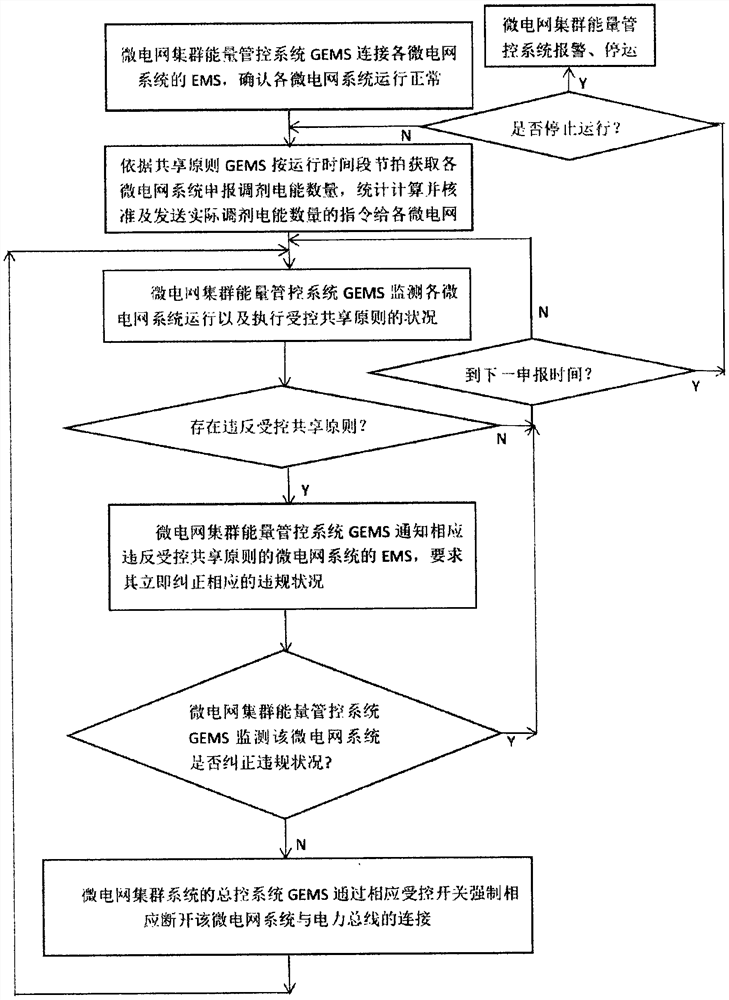

Image

  • Micro-grid cluster system based on fully autonomous controlled sharing and control method
  • Micro-grid cluster system based on fully autonomous controlled sharing and control method

Examples


Embodiment Construction

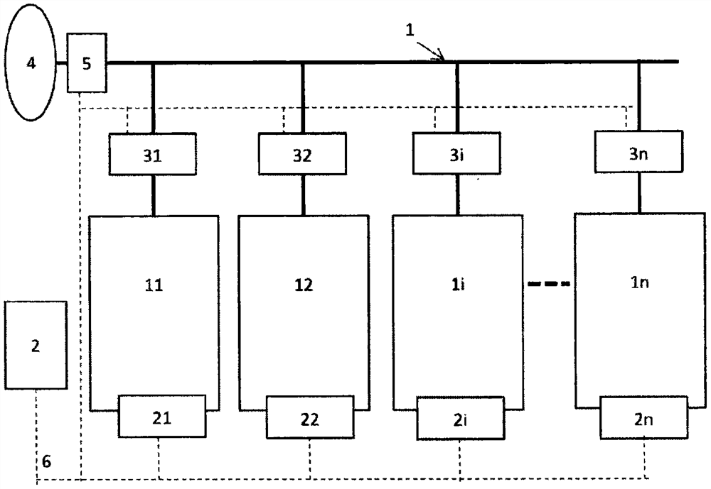
[0023] As an embodiment example, a microgrid cluster system and control method based on fully autonomous controlled sharing will be described with reference to the accompanying drawings, but the described embodiment is that the present invention is applied to a microgrid based on fully autonomous controlled sharing. Some, but not all, embodiments of the cluster system and control method. Based on the embodiments of the present invention, all other embodiments obtained by those of ordinary skill in the art without creative efforts shall fall within the protection scope of the present invention. The technology and solution of the present invention are not limited to the contents given in this embodiment example.

[0024] like figure 1 As shown in the figure, a microgrid cluster system and control method based on fully autonomous controlled sharing is characterized by:

[0025] Under the constraints of the agreed sharing principle, each independently operating microgrid system ...


PUM


Abstract

According to the micro-grid cluster system based on fully autonomous controlled sharing and the control method thereof, through a controlled sharing principle agreed in advance, each micro-grid system operates autonomously under a controlled sharing constraint condition, safety, economy and rationality are considered, 24 hours of each day are taken as a cycle to be divided into a plurality of operation time periods T, and the time periods T are divided into a plurality of time periods T; in each operation period, an electric energy regulation declaration and unified approval controlled execution method is adopted, and electric energy interaction with a power grid is autonomously executed according to approved power and electric quantity limits; each micro-grid system realizes autonomous management and control and operation management through an energy management system (EMS) of the micro-grid system, and according to an electric energy regulation instruction sent by a general control system GEMS of the micro-grid cluster system, each micro-grid system autonomously exchanges electric quantity with a power bus according to a controlled sharing principle. Therefore, each micro-grid system in the micro-grid cluster can fully and autonomously regulate and control the operation and autonomously interact electric energy, the resource utilization rate of each micro-grid system is improved, and the investment benefit is increased.

Description

technical field [0001] The invention belongs to the technical field of microgrids, and in particular relates to a microgrid cluster system and a control method based on fully autonomous and controlled sharing. Background technique [0002] The change of energy structure has promoted the wide application of new energy, especially distributed renewable energy. At the same time, the uncertainty and volatility of distributed renewable energy have added great challenges to the smooth operation of power and grid. In this regard, the use of local microgrids to connect distributed renewable energy, energy storage, and loads together is one of the effective methods for the efficient application of distributed renewable energy. Due to the relatively low energy density of distributed renewable energy, it is suitable for decentralized installation and on-site applications. For example, the use of solar power generation systems constructed by buildings combined with energy storage arbitr...

Claims


Application Information

Patent Timeline
IPC IPC(8): H02J13/00
CPCH02J13/00001H02J13/00002H02J13/00006H02J13/00016
Inventor 周锡卫
Owner 周锡卫
Learn More