Vertical transmission structure

A transmission structure, vertical technology, applied in mixers, dissolving, chemical instruments and methods, etc., can solve the problems of high axial height, large space occupation, etc., achieve the reduction of length and height of support seat, compact structure, and solve leakage problems. Effects of oil problems

Pending Publication Date: 2022-08-02
南京武岳机械设备有限责任公司
View PDF0 Cites 0 Cited by
  • Summary
  • Abstract
  • Description
  • Claims
  • Application Information

AI Technical Summary

Problems solved by technology

[0003] In order to solve the existing problems of high axial height, large space occupation and oil leakage risk, the present invention provides a vertical transmission structure, which can reduce the axial height, save space, and solve the problem of oil leakage at the same time

Method used


Image

  • Vertical transmission structure
  • Vertical transmission structure

Examples


Embodiment Construction

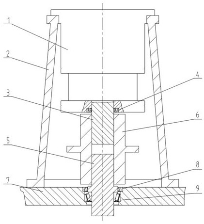
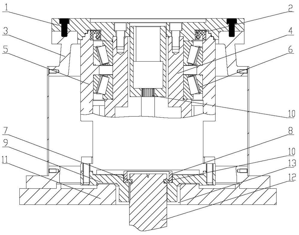
[0011] See figure 2 As shown, a vertical transmission structure includes a reducer, the reducer is mounted on a support base 3, the bottom of the reducer is connected to a stirring shaft 12, the reducer includes a reducer intermediate sleeve 4 and a reducer housing 5, and the reducer housing A reducer bearing 6 is arranged between 5 and the intermediate sleeve 4, the bottom of the reducer housing 5 is connected to the lower flange 9 by bolts, a stepped hole is opened in the middle of the upper end face of the lower flange 9, and a collar is arranged on the stepped surface of the stepped hole. 8. The inner side of the collar is provided with a retaining ring 7. The retaining ring 7 is formed by splicing two halves of half-circles together to form a complete retaining ring. The thickness of the retaining ring can be determined according to the axial force of the stirring shaft 12. After calculation, it is determined that the outer diameter of the baffle ring 7 is limited by the...


PUM


Abstract

The invention relates to the technical field of vertical stirring equipment driving devices, in particular to a vertical transmission structure which can reduce axial height, save space and solve the problem of oil leakage, a speed reducer is installed on a supporting seat, the bottom of the speed reducer is connected with a stirring shaft, and the vertical transmission structure is characterized in that the speed reducer comprises a speed reducer middle sleeve and a speed reducer shell; a speed reducer bearing is arranged between the speed reducer shell and the middle sleeve, a lower flange is connected to the bottom of the speed reducer shell, a stepped hole is formed in the middle of the upper end face of the lower flange, a lantern ring is arranged on the stepped face of the stepped hole, and a baffle ring is arranged on the inner side of the lantern ring. The stirring shaft penetrates through the stepped hole and is connected with the lower flange through a key; and an annular groove matched with the baffle ring is formed in the peripheral surface of the stirring shaft.

Description

technical field [0001] The invention relates to the technical field of a vertical stirring device driving device, in particular to a vertical transmission structure. Background technique [0002] At present, in the field of vertical stirring, the usual structures such as figure 1 As shown, 1 is the reducer, 2 is the support sleeve of the reducer, 3 is the output shaft of the reducer, 4 is the oil seal of the output shaft of the reducer, 5 is the stirring shaft, the output shaft 4 of the reducer and the stirring shaft 5 pass through the coupling 6 Connect and transmit torque, 8 is the oil seal on the stirring shaft, which plays a sealing role, and 9 is the upper end bearing of the stirring shaft, which plays the role of supporting and positioning the stirring shaft; the above structure mainly has two shortcomings: 1. The axial dimension is long and occupies more space Large space, especially inconvenient in vertical use; 2. The output shaft of the reducer is oil-sealed at th...

Claims


Application Information

Patent Timeline
Patent Type & Authority Applications(China)
IPC IPC(8): B01F35/30B01F35/32
CPCB01F35/30B01F35/32B01F2035/352B01F2035/3512
Inventor 陈贵强王玉锁段祥强陆义欣
Owner 南京武岳机械设备有限责任公司
Why Eureka
Try Eureka