Water-cooling heat dissipation device for electrical equipment

A technology for water-cooled heat dissipation and electrical equipment, which is used in cleaning heat transfer devices, lighting and heating equipment, cooling/ventilation/heating renovation, etc. Increase the contact area between the heat pipe and the dust in the air to achieve the effect of promoting the collection efficiency and reducing the reverse flow

Pending Publication Date: 2022-08-02
南通京阳机械科技有限公司
View PDF0 Cites 0 Cited by
  • Summary
  • Abstract
  • Description
  • Claims
  • Application Information

AI Technical Summary

Problems solved by technology

[0003] In the prior art, in order to improve the heat dissipation efficiency during the use of water cooling, the installation method of arranging multiple sets of heat dissipation pipes is usually adopted to increase the heat dissipation contact area of ​​the heat dissipation pipes. Although this i

Method used


Image

  • Water-cooling heat dissipation device for electrical equipment
  • Water-cooling heat dissipation device for electrical equipment
  • Water-cooling heat dissipation device for electrical equipment

Examples


Embodiment 1

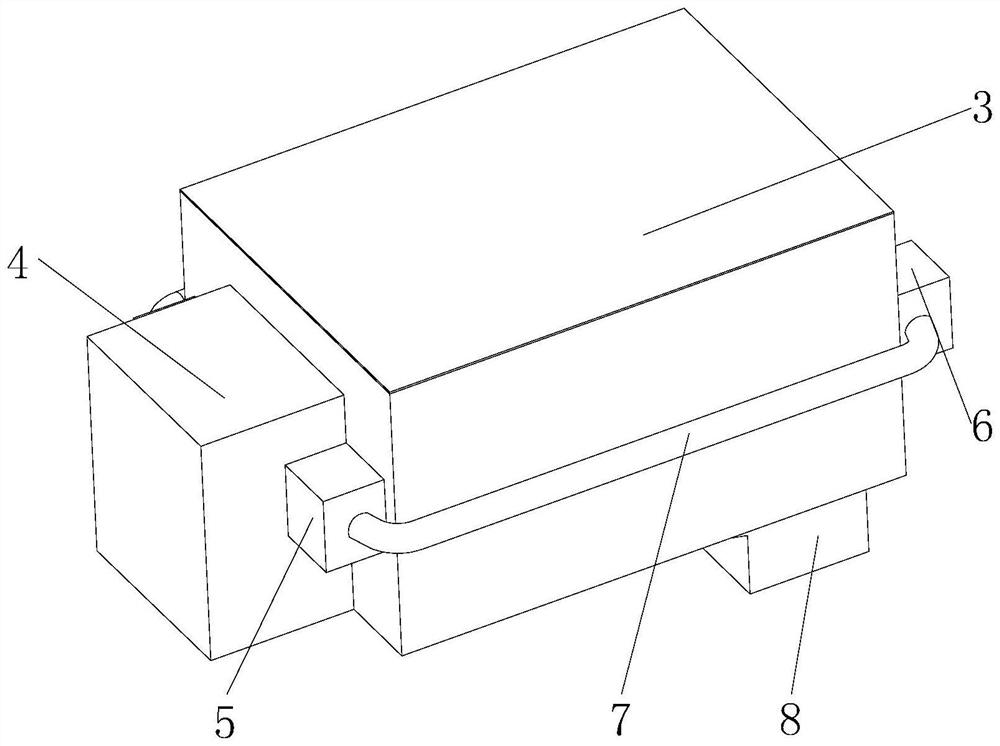
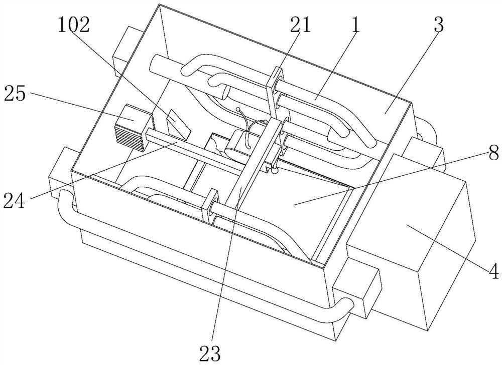
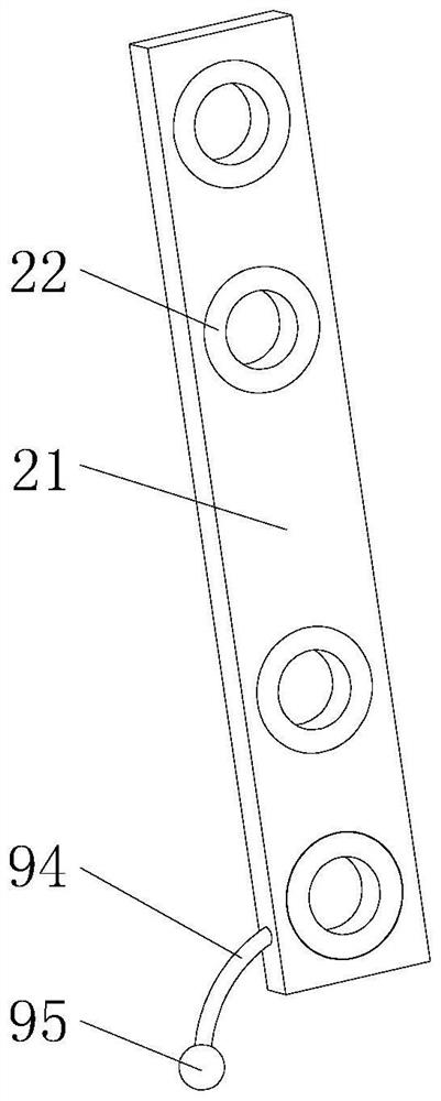
[0029] see Figure 1-6 , the present invention provides a technical solution: a water-cooled heat dissipation device for electrical equipment, including a heat dissipation pipe 1, a cleaning mechanism is provided outside the heat dissipation pipe 1, and the cleaning mechanism includes a socket plate 21, a cleaning soft brush 22, a connecting plate 23, and a telescopic rod 24 and the linear motor 25, the sleeve plate 21 is slidably sleeved on the outer wall of the heat pipe 1, the outer end of the cleaning soft brush 22 is fixedly installed on the sleeve plate 21, the inner end of the cleaning soft brush 22 is set close to the outer wall of the heat pipe 1, and the connecting plate 23 is embedded in the outer wall of the socket plate 21, one end of the telescopic rod 24 is embedded in the outer wall of the connecting plate 23, the other end of the telescopic rod 24 is embedded in the output end of the linear motor 25, and the linear motor 25 is fixedly installed on the inner wal...

Embodiment 2

[0032] like figure 2 , Figure 4 and Figure 5 As shown, on the basis of Embodiment 1, in this embodiment, a collection tank 8 is fixedly installed at the bottom of the electrical box 3, the entrance of the collection tank 8 is arranged in an inclined shape, and a restriction mechanism is provided on the collection tank 8, and the restriction mechanism includes The partition 91, the elastic air bag 92 and the blowing pipe 93, the partition 91 is fixedly installed on the inner wall of the collection tank 8, there is a certain gap between the bottom of the partition 91 and the collection tank 8, the elastic air bag 92 is fixedly installed on the partition 91, blowing The trachea 93 is fixedly installed on the elastic air bag 92, and the bottom of the socket plate 21 is provided with a pressing mechanism. The pressing mechanism includes an arc-shaped fixing rod 94 and a squeezing ball 95. The other end of the arc-shaped fixing rod 94 is fixedly installed with a squeeze ball 95...

Embodiment 3

[0035] like figure 2 and Figure 4 As shown, on the basis of Embodiment 1, in this embodiment, a compaction mechanism is provided on the collection tank 8, and the compaction mechanism includes a compaction plate 101, a sliding rod 102 and a push box 103, and the compaction plate 101 is slidably installed on the On the inner wall of the collection tank 8, the top of the compaction plate 101 and the inner wall of the collection tank 8 are elastically connected by elastic pieces, the bottom of the sliding rod 102 is embedded on the top of the compaction board 101, the sliding rod 102 penetrates and is slidably installed on the bottom of the electrical box 3, and the sliding The upper right end of the rod 102 is set as an inclined surface, the push box 103 is fixedly installed on the outer wall of the socket plate 21, and the sliding rod 102 has magnetism. The collected impurities and dust are compacted to increase the collection capacity.

[0036] When working, when the socke...


PUM


Abstract

The invention discloses a water-cooling heat dissipation device for electrical equipment, and relates to the technical field of electrical appliances. Comprising a heat dissipation pipe, a cleaning mechanism is arranged outside the heat dissipation pipe, the cleaning mechanism comprises a sleeving plate, a cleaning soft brush, a connecting plate, a telescopic rod and a linear motor, the sleeving plate is slidably connected to the outer wall of the heat dissipation pipe in a sleeving mode, the outer end of the cleaning soft brush is fixedly installed on the sleeving plate, and the inner end of the cleaning soft brush is arranged close to the outer wall of the heat dissipation pipe; the connecting plate is fixedly embedded in the outer wall of the sleeving plate, one end of the telescopic rod is fixedly embedded in the outer wall of the connecting plate, and the other end of the telescopic rod is fixedly embedded in the output end of the linear motor. According to the water-cooling heat dissipation device for the electrical equipment, the cleaning mechanism is arranged on the heat dissipation pipe, the sleeving plate can drive the cleaning soft brush to clean the outer wall of the heat dissipation pipe, the situation that dust adheres to affect the heat dissipation efficiency of the heat dissipation pipe is prevented, the collecting groove can conveniently collect impurities and dust cleaned by the sleeving plate, and the heat dissipation efficiency is improved.

Description

technical field [0001] The invention relates to the technical field of electrical appliances, in particular to a water-cooled heat dissipation device for electrical equipment. Background technique [0002] The water cooling system utilizes a pump to circulate the coolant in the heat pipe and dissipate heat. The heat-absorbing part on the radiator (called the heat-absorbing box in the liquid cooling system) is used to absorb heat from the computer CPU, north bridge, and graphics card. The heat absorbed by the heat-absorbing part is discharged to the outside of the host through the radiator designed on the back of the fuselage. [0003] In the prior art, in the process of using water-cooled heat dissipation, in order to improve the heat dissipation efficiency, the installation method of arranging multiple groups of heat dissipation pipes is usually used to improve the heat dissipation contact area of ​​the heat dissipation pipes. Although this improves the heat dissipation ef...

Claims


Application Information

Patent Timeline
IPC IPC(8): H05K7/20G06F1/20F28G13/00
CPCH05K7/20218H05K7/20272G06F1/20F28G13/00
Inventor 季杨成
Owner 南通京阳机械科技有限公司
Why Eureka
Try Eureka