Rapid cooling device for intelligent temperature detection for injection molding

An injection molding and rapid cooling technology, applied in the field of injection molds, can solve the problems of lack of temperature adjustment equipment, affecting the quality of material molding, affecting the production cost of workpieces, etc., to avoid cooling efficiency, avoid non-standard molding, and improve molding quality. Effect

Inactive Publication Date: 2022-05-06
深圳市品佳模塑科技有限公司
View PDF1 Cites 0 Cited by
  • Summary
  • Abstract
  • Description
  • Claims
  • Application Information

AI Technical Summary

Problems solved by technology

[0004] During the use of existing injection molds, there is a lack of temperature adjustment equipment. When the high-temperature molten material conducts with the low-temperature medium, it will cause crac

Method used


Image

  • Rapid cooling device for intelligent temperature detection for injection molding
  • Rapid cooling device for intelligent temperature detection for injection molding
  • Rapid cooling device for intelligent temperature detection for injection molding

Examples


Embodiment 1

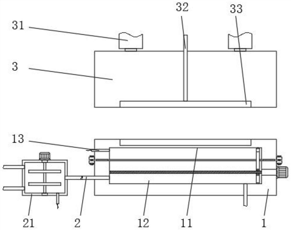
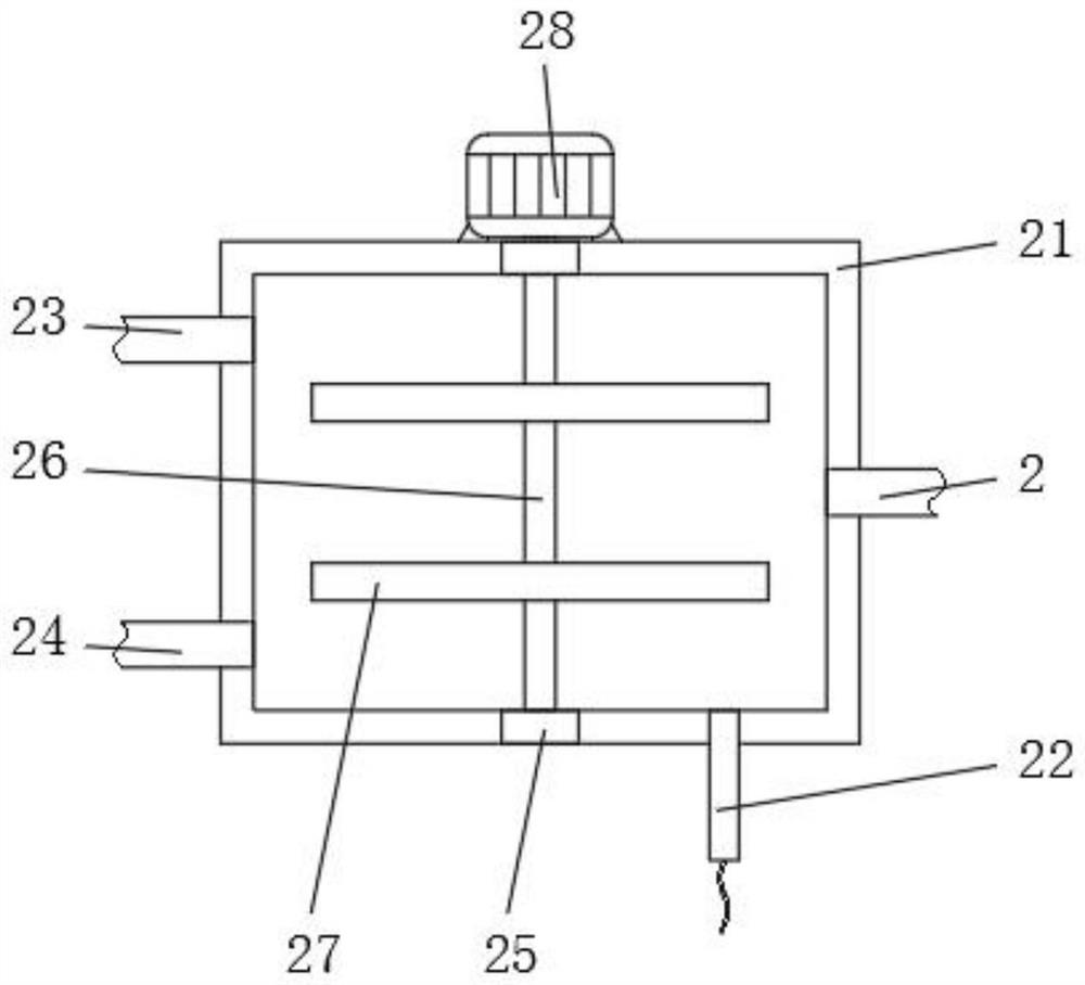
[0028] Embodiment 1: A rapid cooling device for intelligent temperature detection for injection molding, including a base 1, a water inlet pipe 2, an upper mold body 3, a second bearing 4, and a water tank body 21, and the outer wall of the upper end of the base 1 is provided with a lower The mold body 11, the upper outer wall side of the lower mold body 11 is provided with an upper mold body 3, the lower mold body 11 and the outer wall on the opposite side of the base 1 are provided with a cooling groove 12, and the lower end of the inner wall of the cooling groove 12 is plugged with a water inlet pipe 2. The upper mold body 3 and the outer wall of the lower mold body 11 on the opposite side are provided with mold grooves 33, and the mold grooves 33 achieve the purpose of injection molding workpieces;

[0029] A feed pipe 32 is inserted on one side of the outer wall of the upper end of the upper mold body 3, and the feed pipe 32 communicates with the inside of the mold cavity ...

Embodiment 2

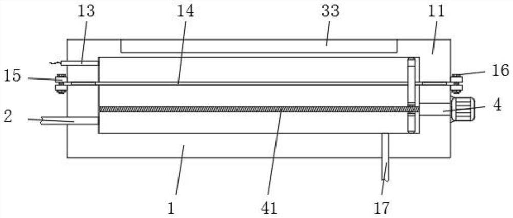
[0036] Embodiment 2: A rapid cooling device for intelligent temperature detection for injection molding, including a base 1, a water inlet pipe 2, an upper mold body 3, a second bearing 4, and a water tank body 21, and a bottom wall is provided on one side of the upper end of the base 1. The mold body 11, the upper outer wall side of the lower mold body 11 is provided with an upper mold body 3, the lower mold body 11 and the outer wall on the opposite side of the base 1 are provided with a cooling groove 12, and the lower end of the inner wall of the cooling groove 12 is plugged with a water inlet pipe 2. The outer wall of the lower end of the lower mold body 11 is attached and fixed with a gasket 14. The gasket 14 is located outside the cooling tank 12, and the gasket 14 is in contact with the outer wall of the upper end of the base 1. The gasket 14 is used to ensure that the base 1 and the lower mold The tightness between the main bodies 11 prevents the cooling liquid inside ...


PUM


Abstract

The intelligent rapid cooling device comprises a base, a water inlet pipe, an upper mold body, a second bearing and a water tank body, a lower mold body is arranged on one side of the outer wall of the upper end of the base, and the upper mold body is arranged on one side of the outer wall of the upper end of the lower mold body; cooling grooves are formed in the outer walls of the opposite sides of the lower die body and the base correspondingly, and water inlet pipes are inserted into the lower ends of one sides of the inner walls of the cooling grooves. By arranging the water tank body, the cooling tank and the supporting frame, the effect of conveniently cooling a workpiece is achieved, the purpose of controlling the temperature of cooling water is achieved by controlling the inlet amount of hot water and cold water, direct low-temperature cooling of molten materials is avoided, it is guaranteed that the materials can be slowly cooled, and the service life of the materials is prolonged. The problems of material cracking and non-standard forming are avoided, the forming quality of materials is improved, the defective product rate is reduced, and the production cost of workpieces is indirectly reduced.

Description

technical field [0001] The invention relates to the technical field of injection molds, in particular to an intelligent temperature detection rapid cooling device for injection molding. Background technique [0002] Injection molding is a method of producing shapes for industrial products. Products usually use rubber injection molding and plastic injection molding. Injection molding can also be divided into injection molding molding method and die-casting method. Injection molding machine is the main molding equipment for making thermoplastic or thermosetting materials into various shapes of plastic products using plastic molding molds. Injection molding is realized through injection molding machines and molds. , rubber injection molding is a production method that injects rubber directly from the machine barrel into the model for vulcanization, and plastic injection molding is a method of plastic products. The molten plastic is injected into the mold of the plastic product...

Claims


Application Information

Patent Timeline
IPC IPC(8): B29C45/73B29C45/78B29C45/17
CPCB29C45/73B29C45/78B29C45/1753B29C2945/76531
Inventor 高光升朱鑫越
Owner 深圳市品佳模塑科技有限公司
Why Eureka
Try Eureka