Electric shock type bionic mosquito killer lamp
A mosquito-killing lamp, an ecological imitation technology, which is applied in the directions of devices, cleaning methods and utensils, chemical instruments and methods for capturing or killing insects, and can solve the problems that the performance and practicability of mosquito-killing lamps cannot meet the needs of people. , to achieve the effect of improving performance and practicability, stable and reliable structure use, and guaranteeing effect and quality
- Summary
- Abstract
- Description
- Claims
- Application Information
AI Technical Summary
Problems solved by technology
Method used
Image
Examples
Embodiment 1
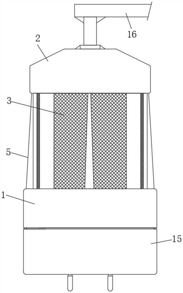
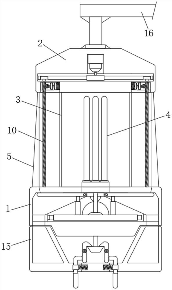
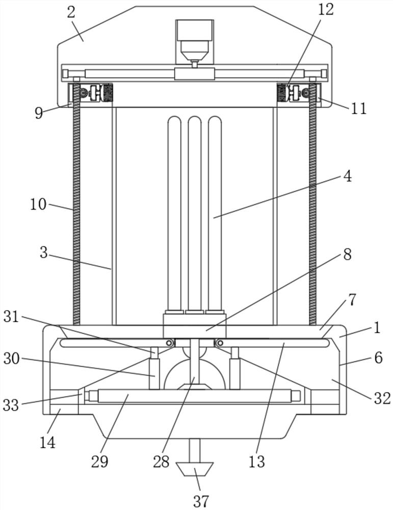
[0028] Example one, by Figure 1 to Figure 8 Provided, the present invention includes a lamp base 1, a lamp top seat 2, a power grid 3 and a mosquito trapping lamp 4, and four fixed plates 5 are installed in a ring-shaped equidistant between the lamp base 1 and the lamp top seat 2, and the top of the lamp base 1 is provided with There is an installation slot 6, the four corners of the upper part of the installation slot 6 are installed with an inverted V-shaped plate 7, a mounting plate 8 is installed between the ends of the four inverted V-shaped plates 7, and the two adjacent inverted V-shaped plates 7 are installed with the installation. An isosceles trapezoid collection port is formed between the groove 6 and the installation plate 8. Through the setting of the inverted V-shaped plate 7, the cleaned worm corpses can effectively slide down into the isosceles trapezoid collection port. Between the top of the V-shaped plate 7 and the bottom of the lamp top seat 2, the mosquit...
Embodiment 2
[0031] The second embodiment, on the basis of the first embodiment, is composed of Figure 2 to Figure 7 Given, the bottom of one of the long worms 10 extends to the inside of the installation groove 6 and is installed with a transmission gear 27, a fixed shaft 28 is installed between the bottom of the installation plate 8 and the bottom of the installation groove 6, and the lower part of the fixed shaft 28 is installed with The large gear 29, the large gear 29 is meshed and connected with the transmission gear 27, the top of the large gear 29 is annularly installed with four large semicircular blocks 30 at equal distances, and the bottoms of the four isosceles trapezoidal baffles 13 are installed with small semicircular blocks 31. The semicircular block 31 is in contact with the large semicircular block 30, so as to effectively drive the isosceles trapezoidal baffle 13 to rotate and shake;
[0032] When the long worm 10 rotates, it will drive the transmission gear 27 to rotat...
Embodiment 3
[0034] Embodiment 3, on the basis of Embodiment 2, is made by image 3 , Figure 7 and Figure 8 Given, the connecting assembly includes two installation shafts 38, the two installation shafts 38 are symmetrically installed in the lower part of the connection groove 35, the surfaces of the two installation shafts 38 are installed with hooks 39, and both sides of the installation shaft 38 are installed with The torsion spring 40, the two ends of the torsion spring 40 are respectively connected with the hook 39 and the installation shaft 38, and the two hooks 39 are movably connected with the conical block 37, so that the connection can be made stably and effectively; the bottom of the collection box 15 is symmetrical There is a cross slot 41, the middle of the two cross slots 41 is installed with a slider 42, a compression spring 43 is installed between the slider 42 and one end of the middle of the cross slot 41, and the top of the slider 42 is installed with L One end of th...
PUM
 Abstract
Description
Claims
Application Information
 - R&D
- Intellectual Property
- Life Sciences
- Materials
- Tech Scout
- Unparalleled Data Quality
- Higher Quality Content
- 60% Fewer Hallucinations
Browse by: Latest US Patents, China's latest patents, Technical Efficacy Thesaurus, Application Domain, Technology Topic, Popular Technical Reports.
© 2025 PatSnap. All rights reserved.Legal|Privacy policy|Modern Slavery Act Transparency Statement|Sitemap|About US| Contact US: help@patsnap.com


