Multi-point plasma spraying coating machine

A technology of plasma and coating machine, applied in spraying device, glass production and other directions, can solve the problem of uneven thickness of glass panels, and achieve the effect of improving material thickness unevenness, spraying stability, and improving uniformity.

Pending Publication Date: 2022-08-05
SHENZHEN DECHENGDA PHOTOELECTRIC MATERIAL CO LTD
View PDF6 Cites 0 Cited by
  • Summary
  • Abstract
  • Description
  • Claims
  • Application Information

AI Technical Summary

Problems solved by technology

[0005] In order to improve the problem of uneven thickness of the glass p

Method used


Image

  • Multi-point plasma spraying coating machine
  • Multi-point plasma spraying coating machine
  • Multi-point plasma spraying coating machine

Examples


Embodiment 1

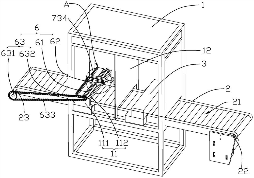
[0035] The embodiment of the present application discloses a multi-point plasma spray coating machine. refer to figure 1 and figure 2 , the coating machine includes a casing 1, a conveyor belt 2, a cleaning mechanism 3, a first spray gun 4 and a second spray gun 5; the casing 1 is set on the ground, the conveyor belt 2 is inserted in the casing 1, and both ends of the conveyor belt 2 extend Outside the casing 1, the length direction of the conveyor belt 2 is the same as the length direction of the casing 1. The conveyor belt 2 has a driving roller 22, a driven roller 23 and a motor. The motor and the driving roller 22 are located at the same end of the conveyor belt 2, and the driven roller 23 is located at the At the other end of the conveyor belt 2, the motor drives the driving roller 22 to rotate, and the driving roller 22 and the driven roller 23 cooperate with each other to drive the conveyor belt 2 to move.

[0036] refer to figure 1 and figure 2 , a separator 12 i...

Embodiment 2

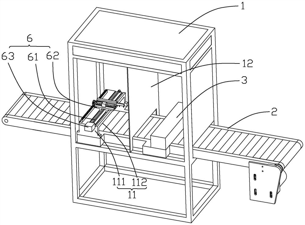
[0043] The embodiment of the present application discloses a multi-point plasma spray coating machine. Different from Example 1, refer to image 3 , the drive source 63 is a servo motor, the servo motor is installed on the top surface of the top plate 112, the servo motor is located at one end of the top plate 112, and one end of the first reciprocating screw is coaxially and fixedly connected to the output shaft of the private server motor.

[0044] The implementation principle of a multi-point plasma spray coating machine in the embodiment of the present application is as follows: the first reciprocating screw is directly driven to rotate by the servo motor, and the sliding speed of the sliding seat 62 can be directly adjusted according to the speed of the conveyor belt 2 to ensure the first spray gun. 4 and the second spray gun 5 finish spraying the corresponding spraying area 21, the conveyor belt 2 advances one spraying area 21, and then the carriage 62 can return to the ...

Embodiment 3

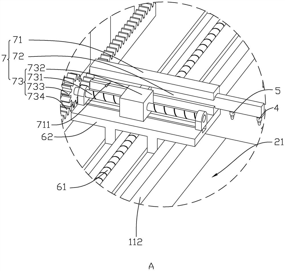
[0046] The embodiment of the present application discloses a multi-point plasma spray coating machine. Unlike Example 2, refer to Figure 4 and Figure 5 , the drive assembly 73 includes a second reciprocating screw 735, a sliding block 732 and a driving motor 736, the sliding block 732 is slidably connected to the top surface of the sliding seat 62, the sliding block 732 moves in the same direction as the conveyor belt 2, and the second reciprocating screw 735 The length direction of the second reciprocating screw 735 is the same as the moving direction of the sliding block 732. The two ends of the second reciprocating screw 735 are rotatably connected to the top surface of the sliding seat 62. 735 is used to drive the sliding block 732 to slide, the driving motor 736 is installed on the top surface of the sliding seat 62, the driving motor 736 is located on the side of the sliding block 732 away from the partition 12, and the second reciprocating screw 735 is coaxially and ...


PUM


Abstract

The multi-point type plasma spraying coating machine comprises a machine shell, a conveying belt, a first spraying gun and a second spraying gun, the conveying belt is arranged in the machine shell in a penetrating mode, and the top face of the conveying belt is divided into a plurality of spraying areas with the same width in the direction perpendicular to the moving direction of the conveying belt; the connecting line direction of the first spray gun and the second spray gun is the same as the moving direction of the conveying belt; a driving mechanism used for driving the first spray gun and the second spray gun to move back and forth in the length direction of the spraying area is installed in the machine shell, and a reciprocating mechanism used for driving the first spray gun and the second spray gun to move in the moving direction of the conveying belt is installed in the machine shell. The movement speed of the first spray gun and the second spray gun in the length direction of the conveying belt is the same as that of the conveying belt, the first spray gun and the second spray gun spray corresponding spraying areas, and meanwhile the conveying belt advances by one spraying area. The method has the effect of improving the non-uniform thickness of the glass panel.

Description

technical field [0001] The invention relates to the technical field of spraying equipment, in particular to a multi-point plasma spray coating machine. Background technique [0002] At present, the use of plasma spray coating machine is more and more extensive, especially in the field of display screen, which is widely used by coating the surface of display screen. [0003] In the related art, multiple rows of glass panels are placed on the conveyor belt of the spray coating machine. During the conveying process of the conveyor belt, the glass panels are first cleaned, and then transported to the bottom of the spray gun for spraying. The movement direction of the spray gun is perpendicular to the conveying direction of the conveyor belt. During the spraying process, the conveyor belt drives the glass panel to move, and the spray gun moves in the direction perpendicular to the movement direction of the glass panel. The trajectory of the material sprayed by the spray gun is wa...

Claims


Application Information

Patent Timeline
IPC IPC(8): B05B13/02B05B13/04
CPCB05B13/0221B05B13/041B05B13/0278Y02P70/10
Inventor 李伟林新冠赵大江
Owner SHENZHEN DECHENGDA PHOTOELECTRIC MATERIAL CO LTD
Why Eureka
Try Eureka