Combined electromagnetic chuck capable of self-centering

An electromagnetic chuck and combined technology, applied in the direction of manufacturing tools, metal processing machinery parts, positioning devices, etc., can solve problems such as deformation, lever damage, accidents, etc., to prevent deformation and damage, prevent temperature rise, reduce The effect of hydraulic pressure

Active Publication Date: 2022-08-05
无锡舰华磁电科技有限公司
View PDF5 Cites 0 Cited by
  • Summary
  • Abstract
  • Description
  • Claims
  • Application Information

AI Technical Summary

Problems solved by technology

[0002] Electromagnetic chuck is a kind of fixture using electromagnetic principle. It is composed of several parts such as magnetic steel, coil, core and shell. It generates magnetic force by energizing the internal coil, and then firmly absorbs the workpiece through the magnetic conduction mechanism. Compared with other mechanical fixtures, electromagnetic chucks can process workpieces such as thin-walled bearings. These workpieces are not easily deformed during processing. In the past, most electromagnetic chucks were usually positioned manually. This positioning method is not only inefficient, but also The accuracy of positioning is difficult to guarantee, and it cannot be applied to mass production of workpieces. In order to improve processing efficiency, combined electromagnetic chucks have appeared on the market
[0003] The existing combined electromagnetic chucks are basically a combination of a chuck and an electromagnetic chuck. In order to prevent the jaws on the chuck from sliding due to the centrifugal force generated by the high-speed rotation of the electromagnetic chuck, most of the combined electromagnetic chucks need to be adjusted inside the chuck. The lever, the first sliding sleeve and the second sliding sleeve apply a lot of pressure to prevent the sliding of the claws, but this method is easy to cause damage and deformation of the lever. When the lever is damaged and deformed, on the one hand, it will This leads to inaccurate positioning of the workpiece. On the other hand, it may not be possible to restrain the jaws, causing the jaws to suddenly separate from the chuck and cause accidents. In addition, the current combined electromagnetic chuck cannot eliminate the gap between the contact surface of the workpiece and the combined electromagnetic chuck , when there is a gap between the workpiece and the combined electromagnetic chuck, in order to prevent the workpiece from detaching from the magnetic device, most of the current operations are to increase the suction force of the combined electromagnetic chuck, but as the suction force of the combined electromagnetic chuck increases, the combined electromagnetic chuck The surface and internal temperature of the electromagnetic chuck will increase accordingly, which will affect the normal processing of the workpiece and easily cause deformation of the workpiece. Direction movement of the magnetic chuck, thus hitting the combined electromagnetic chuck, causing damage to the surface of the combined electromagnetic chuck, further increasing the gap between the workpiece and the combined electromagnetic chuck

Method used


Image

  • Combined electromagnetic chuck capable of self-centering
  • Combined electromagnetic chuck capable of self-centering
  • Combined electromagnetic chuck capable of self-centering

Examples


Embodiment Construction

[0037] The technical solutions in the embodiments of the present invention will be clearly and completely described below with reference to the accompanying drawings in the embodiments of the present invention. Obviously, the described embodiments are only a part of the embodiments of the present invention, rather than all the embodiments. Based on the embodiments of the present invention, all other embodiments obtained by those of ordinary skill in the art without creative efforts shall fall within the protection scope of the present invention.

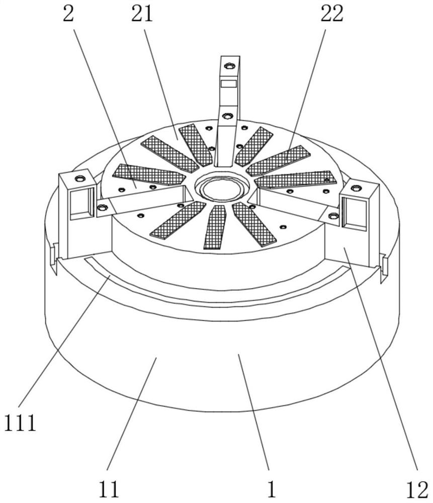
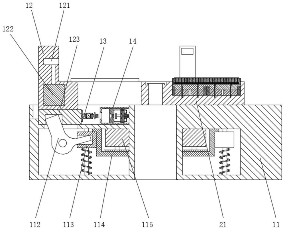
[0038] like Figure 1-Figure 9 As shown in the figure, the combined electromagnetic chuck can self-align the center. The combined electromagnetic chuck includes a positioning device 1 and a magnetic suction device 2. The magnetic suction device 2 is arranged above the positioning device 1. The positioning device 1 includes a chuck 11 and a claw. 12. There are three groups of jaws 12. The three groups of jaws 12 are arranged on the ch...


PUM


Abstract

The invention discloses a combined electromagnetic chuck capable of self-centering, the combined electromagnetic chuck comprises a positioning device and a magnetic suction device, the magnetic suction device is arranged above the positioning device, the positioning device comprises a chuck and three groups of clamping jaws, the three groups of clamping jaws are arranged on the chuck at equal angles, and the magnetic suction device is arranged above the chuck. Compared with an existing electromagnetic chuck, the electromagnetic chuck is provided with the positioning device, a workpiece can be automatically aligned to the center through the positioning device so that machining can be facilitated, and the deviation prevention mechanism and the compensation mechanism are further arranged; on the other hand, when the electromagnetic chuck rotates at a high speed, a part of centrifugal force of the clamping jaws can be offset through the deviation prevention mechanism and the compensation mechanism, so that hydraulic force generated by the hydraulic device is reduced, and the shifting rod is prevented from being deformed and damaged.

Description

technical field [0001] The invention relates to the technical field of electromagnetic chucks, in particular to a combined electromagnetic chuck capable of self-aligning the center. Background technique [0002] The electromagnetic chuck is a fixture that uses the electromagnetic principle. It is composed of several parts such as magnetic steel, coil, movement and shell. It generates magnetic force by energizing the inner coil, and then passes through the magnetic conducting mechanism to firmly adsorb the workpiece. Compared with other mechanical fixtures, the electromagnetic chuck can process thin-walled bearings and other workpieces. These workpieces are not easily deformed during processing. In the past, most of the electromagnetic chucks were usually manually positioned to locate the center. This positioning method is not only inefficient, but also The accuracy of positioning is difficult to guarantee, and it is not suitable for mass production of workpieces. In order to...

Claims


Application Information

Patent Timeline
Patent Type & Authority Applications(China)
IPC IPC(8): B23Q3/154
CPCB23Q3/1543
Inventor 李从俊丁训成孙卫华
Owner 无锡舰华磁电科技有限公司
Why Eureka
Try Eureka