Full-automatic bottle bag disinfection transfer machine and disinfection system
A fully automatic, transfer machine technology, applied in bottling machines, packaging, bottle filling, etc., can solve the problems of cost increase, lack of bottle package transfer disinfection, etc., and achieve the effect of improving efficiency and disinfection efficiency
- Summary
- Abstract
- Description
- Claims
- Application Information
AI Technical Summary
Problems solved by technology
Method used
Image
Examples
Embodiment 1
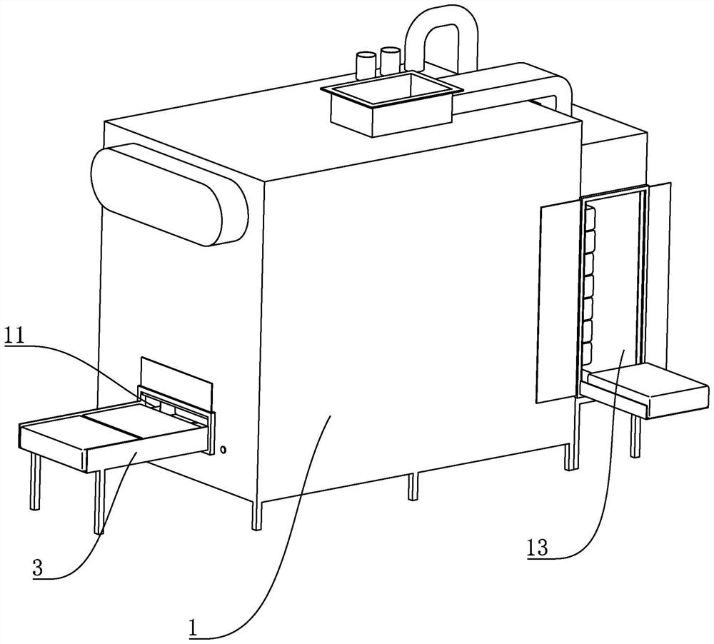
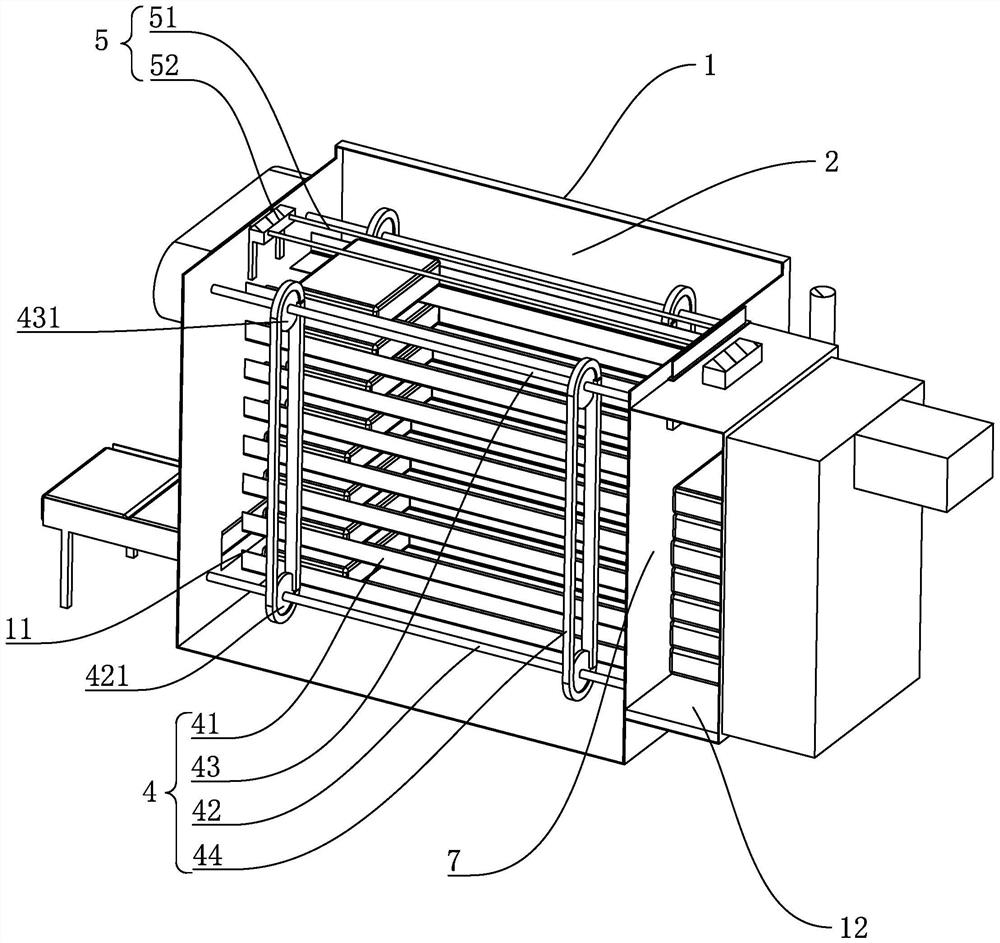
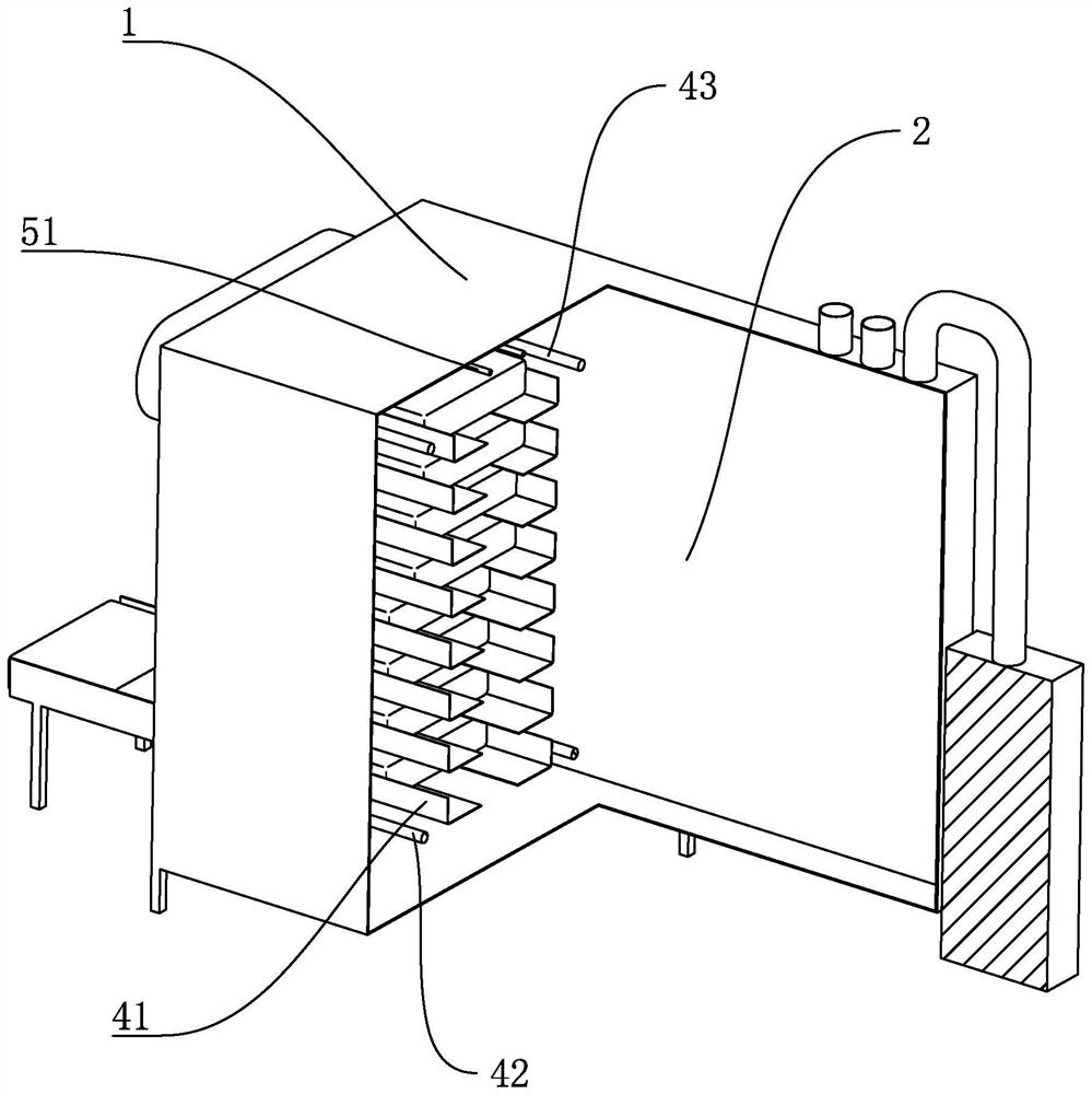
[0046] Example 1: Reference Figure 1 to Figure 11 As shown, a bottle and package automatic disinfection transfer machine, including:
[0047] The sterilization box 1 is provided with a bottle package inlet 11 and a bottle package outlet 12; the bottle package inlet 11 is arranged in the middle of the lower end of one side of the sterilization box 1, and the sterilization box 1 is provided with a sterilization chamber 2 and a buffer chamber 7. , the bottle pack outlet 12 is arranged on the side wall of the buffer chamber 7; the sterilization chamber 2 and the buffer chamber 7 are separated by a baffle plate, and the baffle plate is provided with a sterilization outlet 13, and the bottle bag inlet 11 and the sterilization outlet 13 are respectively provided with The electric door (not shown in the figure) is used to control the opening and closing of the bottle bag inlet 11 and the sterilization outlet 13;
[0048] The feeding device 3 is used to send the bottle packs into the...
Embodiment 2
[0065] Example 2: Reference Figure 5 to Figure 9 The structure of this embodiment is similar to that of Embodiment 1, the difference is that the second discharging device 6 also includes a buffer device.
[0066] The buffer device includes: a transition cylinder 62 and a buffer frame 63;
[0067] The transition cylinder 62, the output end of the transition cylinder 62 is provided with a transition plate 621;
[0068] Buffer frame 63, the buffer frame 63 is arranged along the vertical direction of the buffer chamber 7, the upper end of the buffer frame 63 is provided with an upper rotating shaft 64, there is a certain resistance between the upper rotating shaft 64 and the buffer frame 63, (the generation of resistance can 64 and the buffer frame 63 are connected with a larger diameter, or a damping ring is set between the upper shaft 64 and the buffer frame 63 to increase the resistance of the upper shaft 64 to rotate), and an upper gear 641 is provided on the upper shaft 64;...
PUM
 Abstract
Description
Claims
Application Information
 - R&D
- Intellectual Property
- Life Sciences
- Materials
- Tech Scout
- Unparalleled Data Quality
- Higher Quality Content
- 60% Fewer Hallucinations
Browse by: Latest US Patents, China's latest patents, Technical Efficacy Thesaurus, Application Domain, Technology Topic, Popular Technical Reports.
© 2025 PatSnap. All rights reserved.Legal|Privacy policy|Modern Slavery Act Transparency Statement|Sitemap|About US| Contact US: help@patsnap.com


