Constant-variable multi-way valve and hydraulic system thereof

A multi-way valve and variable technology, which is applied in the direction of fluid pressure actuators, servo motor components, combustion engines, etc., can solve the problem that variable variable pumps cannot play the role of adjusting energy saving effects, and achieve improved action coordination, energy saving, and improved The effect of work efficiency

Active Publication Date: 2022-08-05
XCMG CONSTR MACHINERY
View PDF6 Cites 0 Cited by
  • Summary
  • Abstract
  • Description
  • Claims
  • Application Information

AI Technical Summary

Problems solved by technology

[0004] In order to solve the deficiencies of the prior art, the object of the present invention is to provide a constant variable multi-way valve and its hydraulic system, which solves the problem that the variable variable pump cannot play a role in regulating and saving energy when the fixed variable hydraulic system of the loader is working in the working device in the prior art. problem of effect

Method used


Image

  • Constant-variable multi-way valve and hydraulic system thereof
  • Constant-variable multi-way valve and hydraulic system thereof

Examples


Embodiment 1

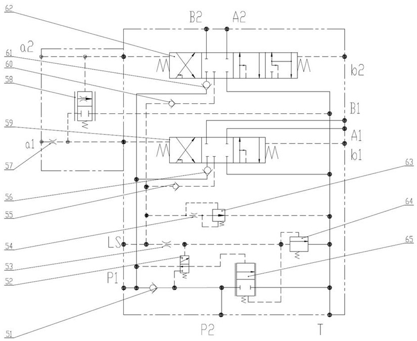
[0041] This embodiment discloses a constant variable multi-way valve 5, combined with figure 1 As shown, it includes a pilot-controlled first main spool 59 with a three-position and closed-center position, a pilot-controlled second main spool 62 with a four-position and closed-center position, and ports P1, P2, LS, and T. , a1 port, a2 port, b1 port, b2 port, A1 port, A2 port, B1 port, B2 port.

[0042] The P1 port is used to connect the variable pump 2, and the P2 port is used to connect the quantitative pump 3.

[0043] The LS port is used to connect with the load feedback port of the variable pump 2 to feed back the load pressure to the variable pump 2, so that the variable pump 2 provides pressure oil according to the feedback pressure signal.

[0044] Port T is connected to hydraulic oil tank 1 for oil return of the hydraulic system.

[0045] The P2 port joins with the P1 port through the confluence check valve 51. The P1 port is connected to the oil inlet oil circuit o...

Embodiment 2

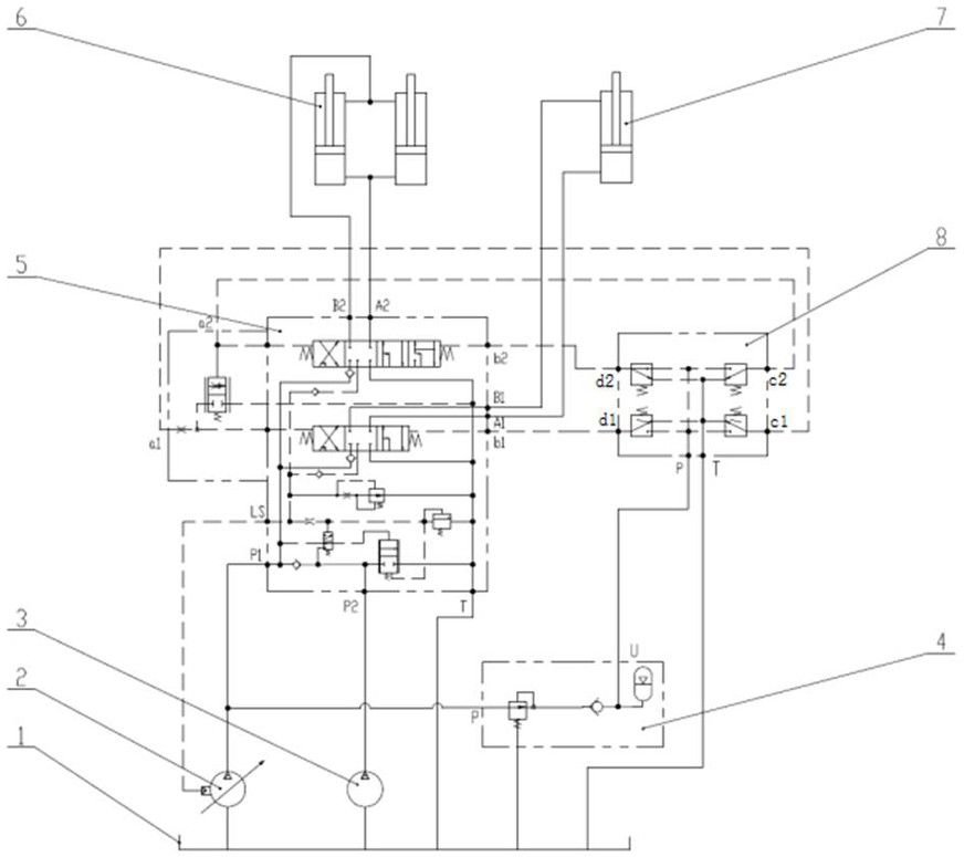
[0055] This embodiment discloses a constant variable hydraulic system of a loader, such as figure 2 As shown, the variable pump 2 draws hydraulic oil from the hydraulic oil tank 1 to supply the P1 port of the fixed variable multi-way valve 5, and the quantitative pump 3 draws hydraulic oil from the hydraulic oil tank 1 to supply the P2 port of the fixed variable multi-way valve 5. The two working oil ports A1 and B1 of the first main spool 59 are respectively connected to the rodless cavity and the rod cavity of the first actuator 6 , and the two working oil ports A2 and B2 of the second main spool 62 The ports are respectively connected with the rodless cavity and the rod cavity of the second actuator 7, and the pilot control oil ports a1, b1, a2 and b2 of the first main spool 59 and the second main spool 62 are respectively connected with the pilot The c1 port, c2 port, d1 port, and d2 port of the valve 8 are connected, the P2 port is connected with the pump port of the qua...


PUM


Abstract

The invention discloses a constant-variable multi-way valve and a hydraulic system thereof, the constant-variable multi-way valve comprises a converging one-way valve, a pilot control valve, an LS throttle valve, a first main valve core, a second main valve core, an LS overflow valve, a converging control valve and a plurality of oil ports, a port P2 converges with a port P1 through the converging one-way valve, the port P2 is simultaneously communicated with an oil inlet of the converging control valve core, and the port P2 is communicated with an oil outlet of the converging control valve core. And an oil outlet of the confluence control valve core is communicated with an oil return port of the constant-variable multi-way valve. A feedback port of the first main valve element and a feedback port of the second main valve element are jointly communicated with an LS port of the constant-variable multi-way valve through a first feedback one-way valve and a second feedback one-way valve, and the LS port is communicated with an inlet of the throttling valve at the same time. A first oil inlet and a second oil inlet of the pilot control valve are communicated with an oil inlet and an oil outlet of the confluence one-way valve respectively, and the oil outlet is communicated with the control end of the confluence control valve. During working, the variable characteristic of the variable pump is fully utilized, energy is saved according to needs, and the composite action is achieved.

Description

technical field [0001] The invention relates to a constant variable multi-way valve and a hydraulic system thereof, belonging to the technical field of engineering machinery hydraulics. Background technique [0002] When the working device of the fixed variable hydraulic system used in the current loader works, the variable pump works in a quantitative state, with full displacement output. At the same time, the existing fixed variable hydraulic systems of loaders mostly use open center distribution valve, which is limited by the structure principle of the distribution valve itself, cannot realize compound action, and the improvement of work efficiency is limited. Throttling loss, resulting in high equipment fuel consumption. [0003] The power of the loader mainly flows in two directions: walking and working. The power matching of the walking and working systems greatly affects the working efficiency and action coordination of the equipment. In the existing loader constant...

Claims


Application Information

Patent Timeline
Patent Type & Authority Applications(China)
IPC IPC(8): F15B13/02F15B13/06F15B13/16
CPCF15B13/02F15B13/06F15B13/16Y02T10/12
Inventor 范小童沈勇郭文明马鹏鹏张安民乔战战宋亚莉李建洋刘奔奔孙志远
Owner XCMG CONSTR MACHINERY
Why Eureka
Try Eureka