
Thermal power generation device for waste incineration power generation

A thermal power generation and waste incineration technology, applied in the direction of incinerators, combustion types, combustion methods, etc., can solve the problems of inconvenient full combustion, unfavorable high-efficiency slag discharge, unfavorable energy recycling work, etc., to achieve convenient regulation and discharge The effects of slag discharge work and convenient energy reuse

Pending Publication Date: 2022-08-05
徐培芳
View PDF2 Cites 0 Cited by
  • Summary
  • Abstract
  • Description
  • Claims
  • Application Information

AI Technical Summary

Problems solved by technology

[0005] There is a phenomenon that the thermal power generation device is not convenient for multiple heat utilization, which is not conducive to the energy recovery work, which will cause certain inconvenience. At the same time, the thermal power generation device is also inconvenient for multi-stage internal gas supply, which is not convenient for full combustion , there is still a phenomenon that is not conducive to efficient slagging, and needs to be improved

Method used


Image

  • Thermal power generation device for waste incineration power generation
  • Thermal power generation device for waste incineration power generation
  • Thermal power generation device for waste incineration power generation

Examples


Embodiment Construction

[0038] The technical solutions in the embodiments of the present invention will be clearly and completely described below with reference to the accompanying drawings in the embodiments of the present invention. Obviously, the described embodiments are only a part of the embodiments of the present invention, rather than all the embodiments. Based on the embodiments of the present invention, all other embodiments obtained by those of ordinary skill in the art without creative efforts shall fall within the protection scope of the present invention.

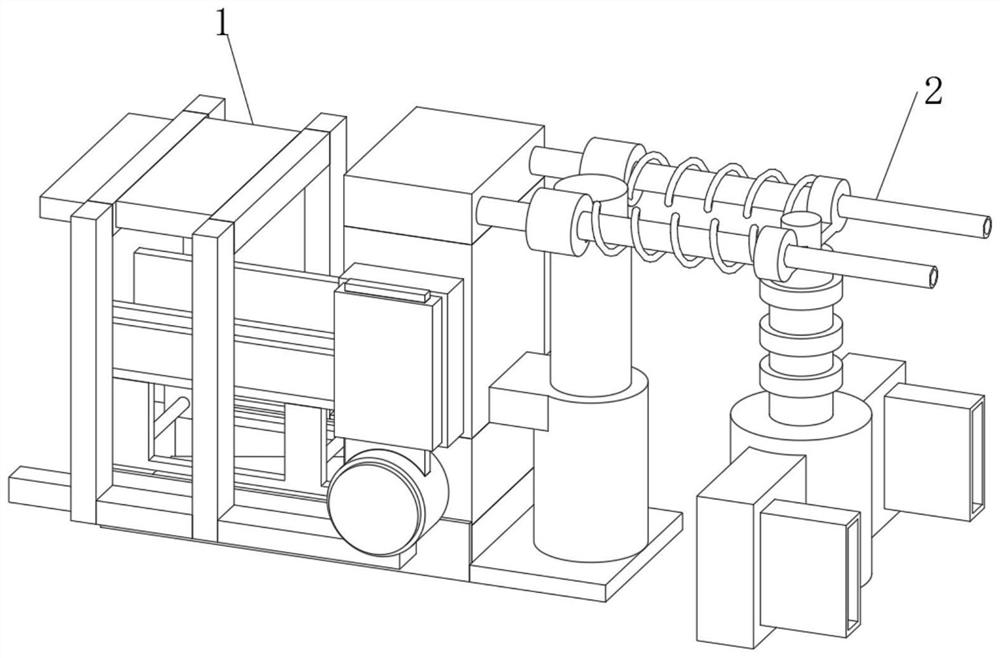
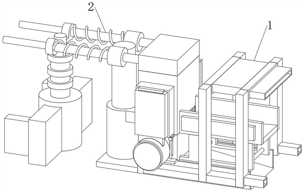
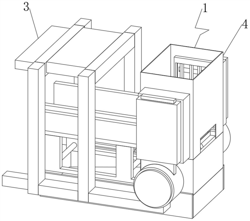
[0039] see Figure 1-10 , the present invention provides a technical solution: a thermal power generation device for waste incineration power generation, comprising a gas supply combustion structure 1, a recycling production structure 2 is connected to the side end position of the gas supply combustion structure 1, and through the gas supply combustion structure 1. The combined connection with the reuse production structure 2 realize...


PUM


Abstract

The thermal power generation device comprises a gas supply combustion structure, the side end position of the gas supply combustion structure communicates with a recycling production structure, the gas supply combustion structure comprises a gas guide part and a treatment part, the gas guide part is arranged on one side of the inner end of the gas supply combustion structure, and the treatment part is arranged on one side of the inner end of the gas supply combustion structure. The side end position of the gas guide component is communicated with the treatment component, the gas guide component comprises a discharge guide pipe, a communicating pipe, a first longitudinal pipe, an external pipe, a communicating header pipe, a protective sealing shell, a communicating conduction vertical pipe, a grating net and a second longitudinal pipe, the communicating pipe is arranged at the top of the inner end of the gas guide component, and the side end of the communicating pipe is communicated with the first longitudinal pipe; the side end of the first longitudinal pipe is communicated with the drainage pipe, the side end of the drainage pipe is communicated with the second longitudinal pipe, and the first longitudinal pipe is communicated between the drainage pipe and the communicating pipe. According to the thermal power generation device for waste incineration power generation, through the arrangement of the recycling production structure, the purpose of recycling heat at the inner end is achieved.

Description

technical field [0001] The invention relates to the technical field of thermal power generation equipment, in particular to a thermal power generation device for waste incineration power generation. Background technique [0002] Waste-to-energy collects all kinds of garbage and sorts them out. Among them: First, high-temperature incineration is performed on those with higher combustion values ​​(which also completely eliminates pathogenic organisms and corrosive organic substances), and the heat energy generated in high-temperature incineration (the generated smoke is treated) is converted into high-temperature steam, which drives the turbine to rotate, Make the generator generate electricity. The second is to ferment and anaerobic process the incombustible organic matter, and finally dry and desulfurize it to produce a gas called methane, also known as biogas. After combustion, the heat energy is converted into steam. The turbine is driven to rotate, which drives the gen...

Claims


Application Information

Patent Timeline
IPC IPC(8): F23G5/00F23G5/44F23G5/46F23J1/00
CPCF23G5/006F23G5/44F23G5/444F23G5/46F23J1/00F23G2206/203Y02E20/12
Inventor 徐培芳
Owner 徐培芳
Learn More