Cable-stayed adhesive force tester

A technology of adhesion and tester, which is applied in the direction of testing material strength by applying stable shear force, testing material strength by applying stable tension/pressure, instruments, etc., and can solve the problem of not being able to truly simulate asphalt pavement in high temperature and rainy areas loading mode etc.

Pending Publication Date: 2022-08-05
TONGJI UNIV
View PDF20 Cites 1 Cited by
  • Summary
  • Abstract
  • Description
  • Claims
  • Application Information

AI Technical Summary

Problems solved by technology

However, in the actual road driving environment, the asphalt mixture is subject to the coupling effect of the vertical gravity load of the vehicle and the horizontal friction force of the tire on the road surface. It can be seen that none of the above four types of test methods can truly simulate the high temperature and rainy areas. Loading mode of asphalt pavement with horizontal force

Method used


Image

  • Cable-stayed adhesive force tester
  • Cable-stayed adhesive force tester
  • Cable-stayed adhesive force tester

Examples


Embodiment 1

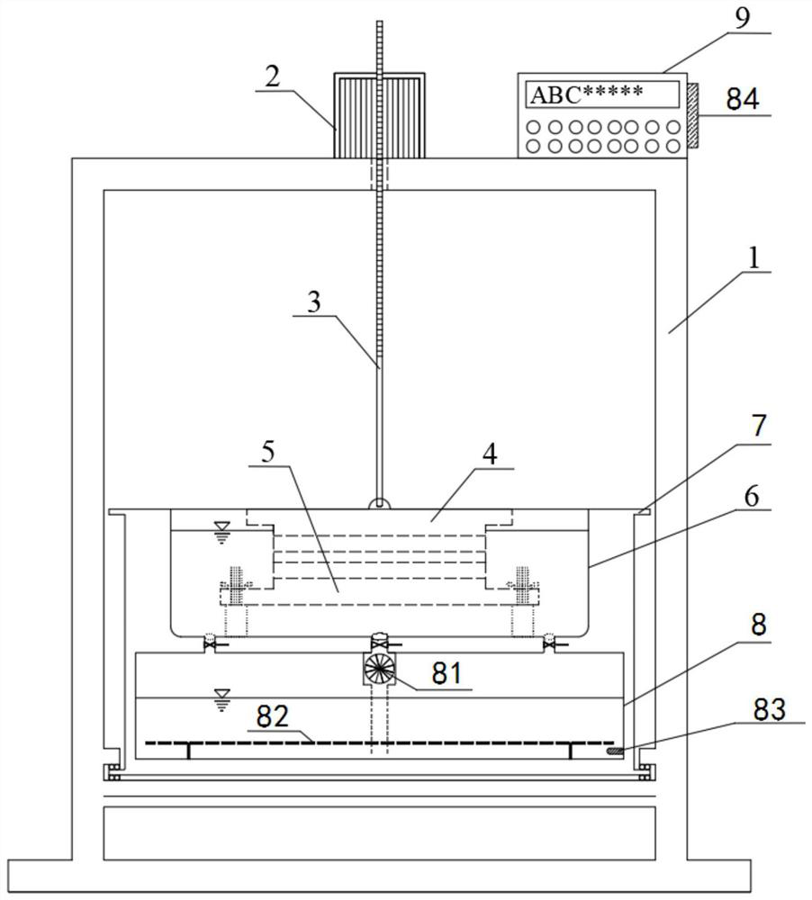
[0045] An oblique pull adhesion tester, comprising a frame 1, a tensioner 2, a pulling rod 3, an upper support plate 4, a lower support plate 5, a water bath container 6 and a rotating bracket 7; the tensioner 2 is installed on the top of the frame 1 In the middle position, the pulling rod 3 passes through the upper beam of the frame 1 and is connected downward to the upper support plate 4, the upper support plate 4 and the lower support plate 5 are the pieces to be tested, and the lower support plate 5 is fixedly installed in the water bath container 6. , the water bath container 6 is embedded in the rotating bracket 7 , and the rotating bracket 7 is slidably installed on the lower beam of the frame 1 .

[0046] The specimen to be tested is a specimen with a slate / upper cladding layer + cementitious material / bonding layer + slate / underlying layer structure. During the test, the water bath container 6 is used for water bath insulation, and the rotating bracket 7 is used to plac...

Embodiment 2

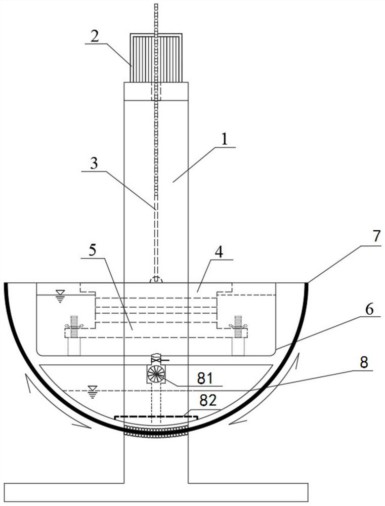
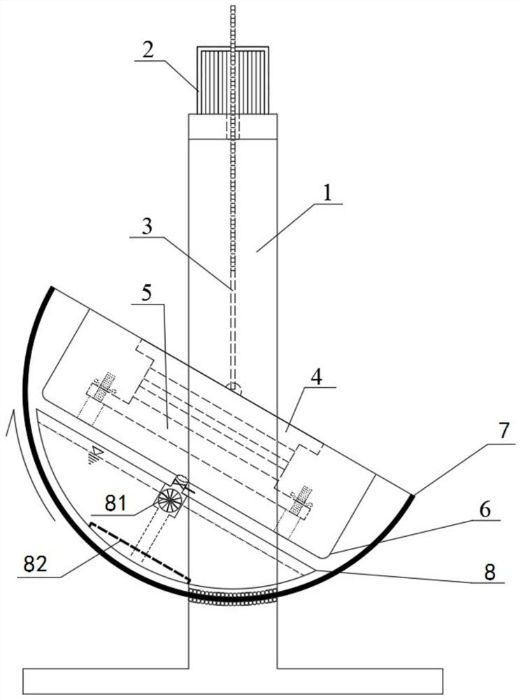
[0048] A diagonal pull adhesion tester, comprising: a frame 1, a tensioner 2, a pulling rod 3, an upper support plate 4, a lower support plate 5, a water bath container 6, a water storage heating container 8, a rotating bracket 7 and a controller 9. The tensioner 2 is installed in the middle position of the top of the frame 1. The pulling rod 3 passes through the upper beam of the frame 1 and is connected downward to the upper support plate 4. The test piece of cementitious material / bonding layer + slate / underlying layer structure, the lower support plate 5 is fixedly installed in the bottom middle position of the water bath container 6, the water bath container 6 is embedded in the upper part of the rotating support 7, the water storage heating container 8 It is installed at the lower part of the rotating support 7 directly below the water bath container 6, the rotating support 7 is slidably installed on the lower beam of the frame 1, the controller 9 is installed on the top ...


PUM


Abstract

The invention relates to a cable-stayed adhesive force tester which comprises a rack (1), a chest expander (2), a drawing rod (3), an upper bearing plate (4), a lower bearing plate (5), a water bath container (6) and a rotating bracket (7), the chest expander (2) is arranged at the top of the rack (1), the drawing rod (3) penetrates through an upper cross beam of the rack (1) and is downwards connected with the upper bearing plate (4), a test piece is arranged between the upper bearing plate (4) and the lower bearing plate (5), the lower bearing plate (5) is fixedly arranged in the water bath container (6), the water bath container (6) is embedded in the rotating bracket (7), and the rotating bracket (7) is arranged on a lower cross beam of the rack (1) in a sliding manner. Compared with the prior art, the device can realize bonding failure between asphalt and aggregate and between asphalt and pavement layers under the coupling action of tensile stress and shear stress, and truly simulate the real loading mode of the asphalt pavement in a high-temperature rainy region under the action of horizontal force; the current situation that the asphalt and aggregate adhesion and interlayer adhesion testing method at the present stage is single and does not conform to the actual situation is effectively overcome.

Description

technical field [0001] The invention relates to the technical field of pavement material testing equipment, in particular to a cable-pull adhesion tester. Background technique [0002] As we all know, the asphalt mixture as the mainstream paving material is a multi-phase mixed material composed of asphalt and mineral materials. Interfacial phase (interface between asphalt and aggregate). In terms of force, the reinforcement phase forms a skeleton to withstand vehicle loads, the matrix phase fills in between the reinforcement phases to transfer loads, and the interface phase formed between the reinforcement phase and the matrix phase is the link between the two. The morphology is different from the matrix part, its structure is relatively loose, and its strength is low. Under the action of external factors, cracks are prone to appear in this area, which is the key factor to determine the synergy between the two. In other words, the adhesion between asphalt and aggregate int...

Claims


Application Information

Patent Timeline
Patent Type & Authority Applications(China)
IPC IPC(8): G01N3/08G01N3/24G01N3/04G01N3/02
CPCG01N3/08G01N3/24G01N3/04G01N3/02G01N2203/0026G01N2203/0032G01N2203/0226G01N2203/0282G01N2203/04G01N2203/0676Y02E10/50
Inventor 刘黎萍刘宁
Owner TONGJI UNIV
Why Eureka
Try Eureka