
Insulating coating coating device for wire processing

A technology of insulating coating and coating device, which is applied in the direction of insulating conductors/cables, circuits, electrical components, etc., can solve the problems of reduced drying structure performance, reduced drying efficiency, difficult maintenance of control components, etc.

Pending Publication Date: 2022-08-05
郭华民
View PDF0 Cites 0 Cited by
  • Summary
  • Abstract
  • Description
  • Claims
  • Application Information

AI Technical Summary

Problems solved by technology

[0003] However, as far as the current traditional insulating coating coating device for wire processing is concerned, although it can also be dried after coating when the wire insulating layer is coated, its drying structure will deteriorate after being used for a period of time. Lead to performance degradation, which in turn leads to a reduction in drying efficiency;
[0004] At present, the coating liquid needs to be supplied under the action of electric components and control components during coating, which leads to an increase in equipment costs, and it is difficult to repair the control components if they are damaged

Method used


Image

  • Insulating coating coating device for wire processing
  • Insulating coating coating device for wire processing
  • Insulating coating coating device for wire processing

Examples


Embodiment 1

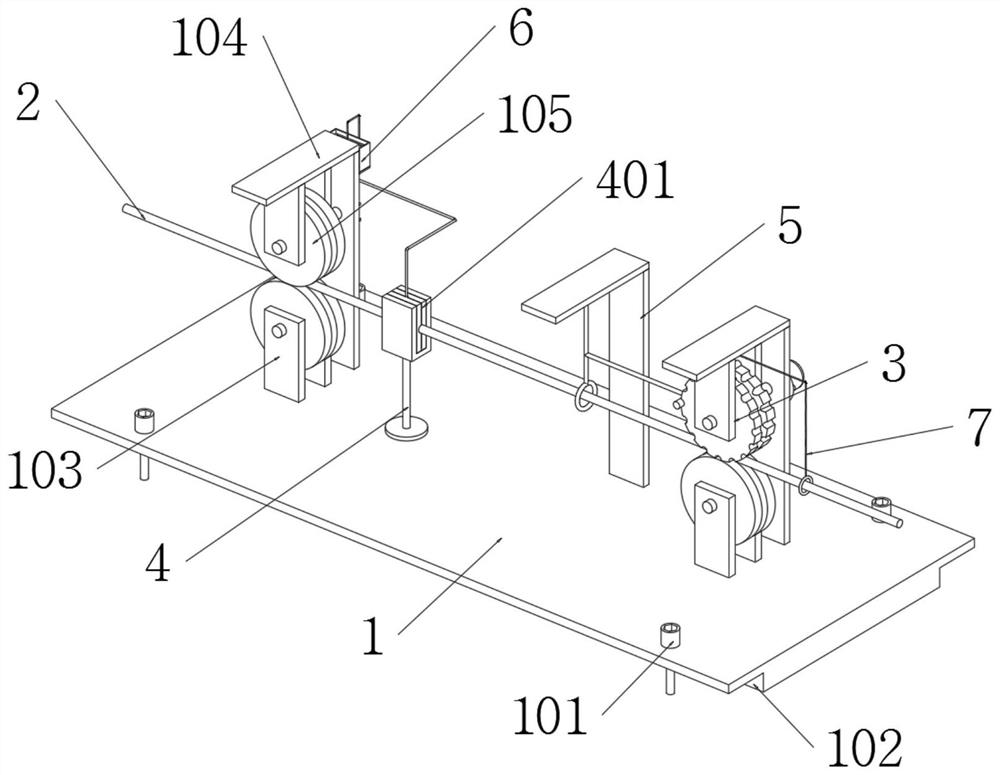
[0046] The present invention provides an insulating coating coating device for wire processing, comprising: a base 1, a driving part 3 and a drying part 5;

[0047] The base 1 is fixedly connected to the workbench through four fixing bolts 101, and two supporting wheels A103 are installed on the top surface of the base 1;

[0048] A mounting bracket A104 is installed on the top surface of the base 1, and the mounting bracket A104 is aligned with the supporting wheel A103 on the left side, and a supporting wheel B105 is installed on the mounting bracket A104;

[0049] Wire 2 is transported between the roller B105 and the roller A103;

[0050]The driving part 3 is composed of a mounting frame B301, a driving wheel 302, a driving motor 303 and a groove 304, and the mounting frame B301 is installed on the top surface of the base 1;

[0051] A bracket 4 is installed on the top surface of the base 1;

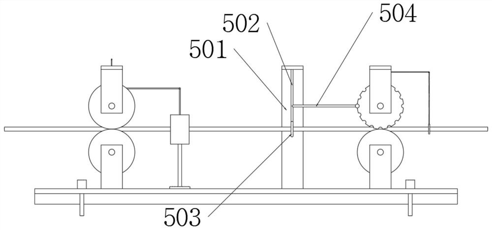
[0052] The drying part 5 consists of a frame body 501, a connecting rod 502, a ...

Embodiment 2

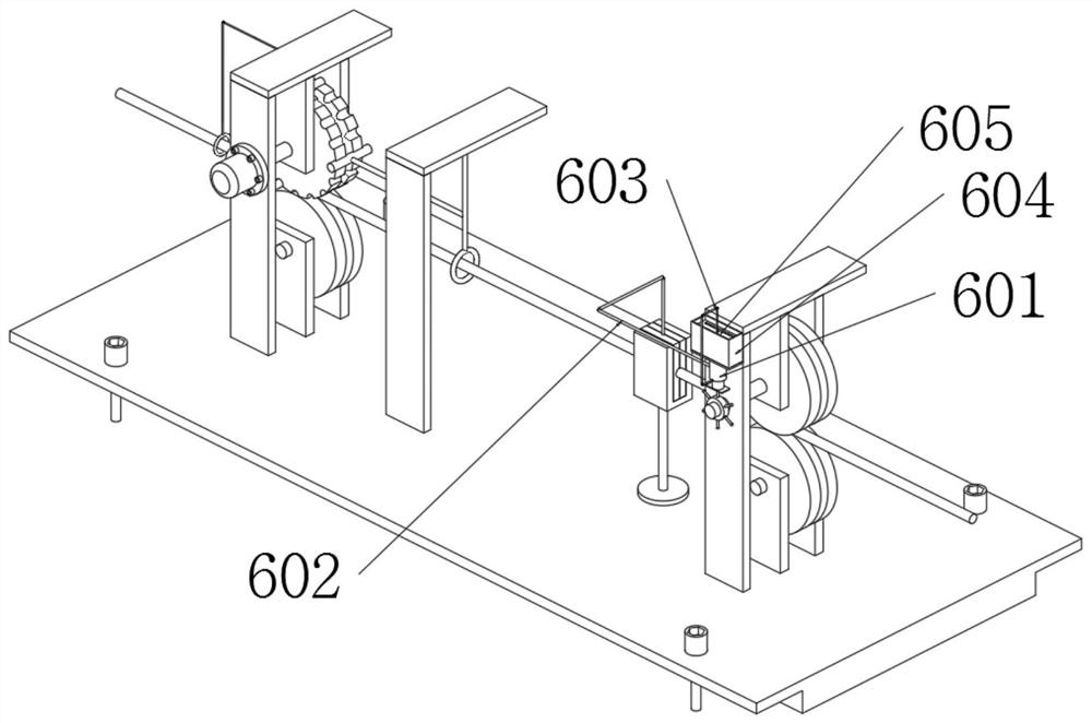
[0065] An insulating coating coating device for wire processing, further comprising: a supplying part 6; 601 is mounted on mounting bracket A104.

[0066] Furthermore, according to embodiments of the present invention, such as figure 2 As shown, the liquid storage box 604 is fixedly connected to the rear end face of the mounting bracket A104;

[0067] The piston bottle 601 is connected with a nozzle 602 and a water inlet pipe, and the water inlet pipe is connected with the liquid storage box 604, and the head end of the nozzle 602 is inserted into the coated cotton 401;

[0068] A check valve is installed in the spray pipe 602 and the water inlet pipe, so that the automatic liquid supply of the coated cotton 401 can be realized when the piston bottle 601 is stretched and retracted.

[0069] Furthermore, according to embodiments of the present invention, such as figure 2 As shown, the piston bottle 601 is welded with a connecting arm 603, and the tail end of the connecting...

Embodiment 3

[0075] An insulating coating coating device for wire processing, further comprising: an auxiliary part 7 ;

[0076] Furthermore, according to embodiments of the present invention, such as Image 6 As shown, the telescopic bottle 701 is fixedly connected to the bottom end surface of the mounting frame B301, and the telescopic bottle 701 is connected with a connecting pipe 702; the connecting pipe 702 is connected with a spray head 703, and the spray head 703 is a ring structure; the inside of the spray head 703 is opened in a circular array shape There are air jet holes, and the nozzle 703 is sleeved on the outside of the wire 2;

[0077] A force block 704 is installed at the head end of the telescopic bottle 701, and the force block 704 is elastically clamped with the groove 304, and when the driving wheel 302 rotates, the telescoping bottle 701 continuously expands and contracts under the action of the force block 704 and the groove 304 Then, at this time, the gas in the tel...


PUM


Abstract

The invention provides an insulating coating coating device for wire processing, which relates to the technical field of wire processing and comprises a base, a driving part, a drying part, a supply part and an auxiliary part, the base is fixedly connected to the workbench through four fixing bolts, and two riding wheels A are installed on the top end face of the base. A mounting frame A is mounted on the top end face of the base, the mounting frame A is aligned with the riding wheel A on the left side, and a riding wheel B is mounted on the mounting frame A. A connecting rod is welded to the bottom end face of the frame body, and a heating wire is installed at the tail end of the connecting rod. The heating wire is in an annular state after deformation, the heating wire is connected to the outer side of the electric wire in a sleeving mode, and the heating wire is located at the position 20 cm away from the right side of the coating cotton, so that when the electric wire moves, automatic drying of the electric wire can be achieved through the heating wire, and the problem that even though drying can be conducted after coating is conducted when the electric wire insulating layer is coated is solved. However, after a drying structure is used for a period of time, the performance is reduced, and then the drying efficiency is reduced.

Description

technical field [0001] The invention relates to the technical field of wire processing, in particular to an insulating coating coating device for wire processing. Background technique [0002] When the wire is processed, it is necessary to coat the surface with an insulating coating, so as to avoid electric shock for the staff during maintenance or layout. [0003] However, as far as the current traditional insulation coating coating device used for wire processing is concerned, although the wire insulation coating can be dried after coating, the drying structure will be damaged after a period of use. This leads to a decrease in performance, which in turn leads to a decrease in drying efficiency; [0004] Currently, the coating liquid needs to be supplied under the action of an electric element and a control element during coating, which leads to an increase in equipment cost, and if the control element is damaged, it is difficult to maintain. SUMMARY OF THE INVENTION ...

Claims


Application Information

Patent Timeline
IPC IPC(8): H01B13/16H01B13/30
CPCH01B13/165H01B13/30Y02P70/10
Inventor 郭华民
Owner 郭华民
Learn More