Dry-type high-frequency high-voltage transformer

A high-frequency, high-voltage, transformer technology, applied in the field of transformers, can solve the problem of slowing down the heat dissipation efficiency of dry-type transformers, and achieve the effect of facilitating cooling and improving heat dissipation efficiency

Pending Publication Date: 2022-08-05
冯秀君
View PDF0 Cites 0 Cited by
  • Summary
  • Abstract
  • Description
  • Claims
  • Application Information

AI Technical Summary

Problems solved by technology

[0003] In hot summer, when the outside temperature is high, the dry-type transformer will inhale the outside air when dissipating heat, but the outside air is in a relatively hot state, and the hot air enters the box of the dry-type transformer, resulting in heat dissipation of the dry-type transformer Efficiency slows down

Method used


Image

  • Dry-type high-frequency high-voltage transformer
  • Dry-type high-frequency high-voltage transformer
  • Dry-type high-frequency high-voltage transformer

Examples


no. 2 example

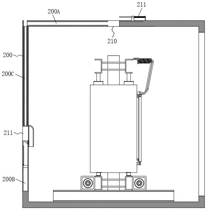
[0052] In the second embodiment, considering that it is easy to encounter wind when it rains, the wind easily blows the rain into the exhaust hole 210 and the sealing member 211, causing the liquid to enter the box 200. For this, please refer to Figure 5 As shown in the figure, a connecting plate 230 is fixedly arranged at the bottom of the protective plate 216, the connecting plate 230 has a ring structure, and a straight rod 231 is disposed at the bottom of the connecting plate 230. A compression spring 232 is arranged between one end of the body 200 and the top inner wall of the box body 200. The rainwater enters the liquid collecting tank, and the guard plate 216 is moved down by gravity, so that the bottom end of the connecting plate 230 is in contact with the top of the box body 200. At this time, the exhaust hole 210 is cut off by the protective plate 216 and the connecting plate 230, and cannot communicate with the outside world, so the gas can only enter the gas deliv...

no. 3 example

[0054] In the third embodiment, considering that the fan 112 blows upwards from the bottom, and the wind becomes hotter during the process of blowing from the bottom to the top, the heat dissipation performance of the top of the transformer body 100 is poor. Therefore, as Figure 8-Figure 11 As shown, the bottom of the liquid storage chamber 200B is fixedly provided with a connection spring 251, the top of the connection spring 251 is provided with a carrier plate 250, the top of the carrier plate 250 is provided with two straight plates 252, and the floating block 214 is located between the two straight plates 252. During the time, the top of the floating block 214 is rotatably connected with the bottom end of the partition plate 215, a gap 253 is formed on the inner wall of the box body 200 on the side of the liquid storage cavity 200B, and a storage cavity 200E is opened on the inner wall of the box body 200 at the bottom of the gap 253. A sealing plate 254 is slidably arran...


PUM


Abstract

The invention relates to a transformer, in particular to a dry-type high-frequency high-voltage transformer. The transformer comprises a transformer body and a box body used for protecting the transformer body, the transformer body is installed in the box body, an exhaust hole is formed in the top of the box body, a protection plate used for protecting the exhaust hole is arranged above the exhaust hole, a sealing piece is arranged on the top of the box body, and the sealing piece controls the exhaust hole according to temperature changes. According to the dry-type high-frequency high-voltage transformer, when the outside air temperature is high, rainwater enables the partition plates to move upwards to penetrate through the baffles and the air inlet holes, outside air cannot enter the box body, internal circulation of the air in the box body is achieved, meanwhile, the circulating air is cooled, and the heat dissipation efficiency of the transformer body is improved.

Description

technical field [0001] The invention relates to a transformer, in particular to a dry-type high-frequency high-voltage transformer. Background technique [0002] Dry-type transformers are widely used in local lighting, high-rise buildings, airports, terminal CNC machinery and equipment, etc. Simply speaking, dry-type transformers refer to transformers whose iron cores and windings are not immersed in insulating oil. The cooling methods are divided into natural air cooling (AN) and forced air cooling (AF). Under natural air cooling, the transformer can run continuously for a long time under the rated capacity. When forced air cooling, the output capacity of the transformer can be increased by 50%. It is suitable for intermittent overload operation or emergency accident overload operation; due to the large increase of load loss and impedance voltage during overload, it is in a non-economic operation state, so it should not be in continuous overload operation for a long time....

Claims


Application Information

Patent Timeline
Patent Type & Authority Applications(China)
IPC IPC(8): H01F27/02H01F27/08
CPCH01F27/025H01F27/085
Inventor 冯秀君
Owner 冯秀君
Why Eureka
Try Eureka