
Pick fault detection method, detection device and use method

A technology of fault detection and cutting teeth, which is applied in the direction of measuring devices, mining devices, cutting machinery, etc., can solve the problems that affect the coal breaking efficiency of the shearer, the poor working conditions, and the working of the coal mining drum with diseases, so as to achieve long-term prevention The effect of working with sickness in time, avoiding overdue service, and reducing the difficulty of maintenance

Pending Publication Date: 2022-08-09
SHANDONG UNIV OF SCI & TECH
View PDF0 Cites 1 Cited by
  • Summary
  • Abstract
  • Description
  • Claims
  • Application Information

AI Technical Summary

Problems solved by technology

[0002] As an important part in the mining process, picks are subject to harsh working conditions and are prone to damage
As far as the existing technology is concerned, the pick is directly installed in the tooth seat, and a single pick does not have the fault detection function, so the fault of a single pick is often not found in time, resulting in the coal mining drum working with diseases, which seriously affects Shearer Coal Breaking Efficiency
If the method of regular batch replacement is adopted, some picks that have not reached their service life will inevitably be replaced together, resulting in waste of labor and materials, and increasing the operating cost of the coal mine

Method used


Image

  • Pick fault detection method, detection device and use method
  • Pick fault detection method, detection device and use method
  • Pick fault detection method, detection device and use method

Examples


Embodiment Construction

[0024] Below in conjunction with accompanying drawing and embodiment, the present invention will be further described:

[0025] In the present invention, unless otherwise expressly specified and limited, the terms "installed", "connected", "connected", "fixed" and other terms should be understood in a broad sense, for example, it may be a fixed connection or a detachable connection , or integrated; it can be directly connected or indirectly connected through an intermediate medium, and it can be the internal connection of two elements or the interaction relationship between the two elements. For those of ordinary skill in the art, the specific meanings of the above terms in the present invention can be understood according to specific situations.

[0026] In the description of the present invention, it should be understood that the terms "center", "length", "upper", "lower", "front", "rear", "left", "right", "vertical", The orientation or positional relationship indicated by ...


PUM


Abstract

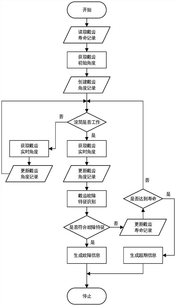
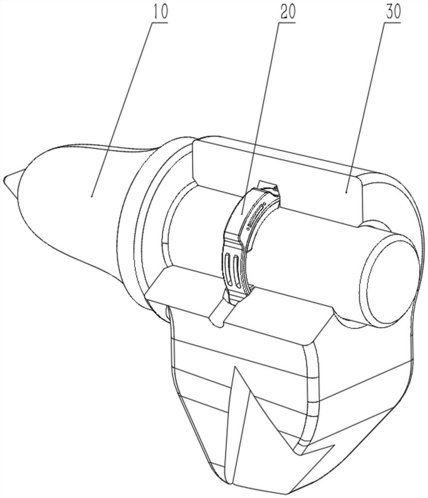
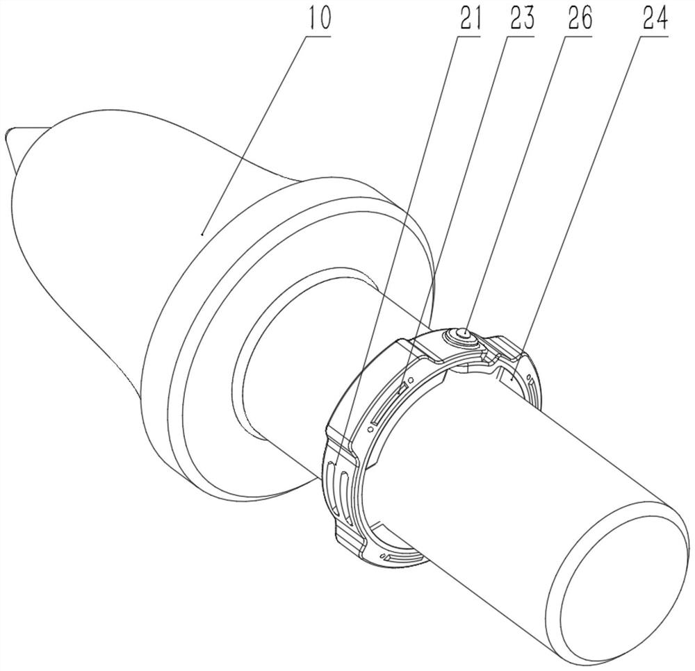
The invention relates to the field of intelligent coal mining equipment, in particular to a cutting tooth fault detection method, a detection device, a use method and a cutting tooth fault detection method, aiming at each cutting tooth, a detection device is correspondingly arranged, the angular position information of the cutting tooth in the cutting process is detected, a curve of the angular position changing along with time is generated, and feature recognition is carried out on the curve. The cutting tooth fault detection device comprises a cutting tooth detection unit and a maintenance terminal, the cutting tooth detection unit is arranged corresponding to each cutting tooth, the cutting tooth detection unit comprises a signal generation ring and a tooth holder, the signal generation ring is arranged outside the cutting tooth in a sleeving mode and rotates together with the cutting tooth, the signal generation ring is arranged in the tooth holder, a permanent magnet is arranged on the signal generation ring, and the signal generation ring is connected with the maintenance terminal. A Hall sensor is arranged in the tooth holder. Self-sharpening of the cutting teeth is utilized, fault and service life monitoring of a single cutting tooth is achieved, long-time work with faults of a roller of the coal mining machine is effectively prevented, the position of the faulted cutting tooth is rapidly positioned, the maintenance difficulty is reduced, the utilization rate of the cutting teeth is increased, and the operation cost of a coal mine is reduced.

Description

technical field [0001] The invention relates to the field of intelligent coal mining equipment, in particular to a method for detecting faults of a pick, a detecting device and a method for using the same. Background technique [0002] As an important part in the mining process, the pick is very easy to be damaged due to harsh working conditions. As far as the prior art is concerned, the pick is directly installed in the tooth holder, and a single pick does not have a fault detection function, so the fault of a single pick cannot be found in time, resulting in the malfunction of the coal mining drum, which seriously affects the The coal breaking efficiency of the shearer. If the method of regular batch replacement is adopted, some of the picks that have not reached their service life will inevitably be replaced together, resulting in waste of labor and materials, and increasing the operating cost of coal mines. SUMMARY OF THE INVENTION [0003] The present invention aims...

Claims


Application Information

Patent Timeline
Patent Type & Authority Applications(China)
IPC IPC(8): E21C35/18E21F17/18G01M13/00
CPCE21C35/18E21F17/18G01M13/00
Inventor 高魁东陈晟曾庆良孙利青尉洪新孟凡盛王鑫宇张志华
Owner SHANDONG UNIV OF SCI & TECH
Learn More