Pipe piece posture adjusting device of pipe piece erector
A technology for adjusting device and segment assembly, which is applied to safety devices, shaft equipment, and final product manufacturing, etc., and can solve problems such as the lack of fine-tuning segments, segment dislocation, and segment assembly equipment that does not have the function of fine-tuning.
- Summary
- Abstract
- Description
- Claims
- Application Information
AI Technical Summary
Problems solved by technology
Method used
Image
Examples
Embodiment 1
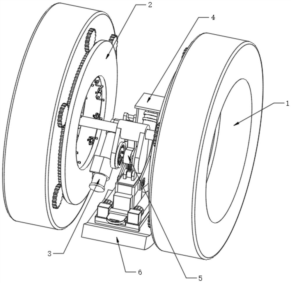
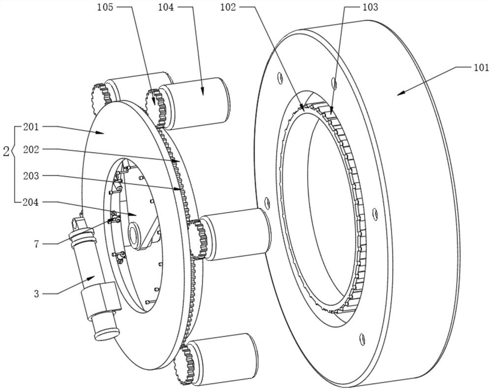
[0039] Refer to the attached image 3 , the circular transport mechanism 1 also includes a ring support frame 101, the inner side of the ring support frame 101 is fixedly provided with an inner convex frame 102, the outer surface of the inner convex frame 102 is equidistantly rotated and installed with a roller 103, and the inner side of the ring support frame 101 is installed A motor one 104 is fixedly installed at equal distances, and a gear one 105 is fixedly installed at the output ends of the motor one 104 .
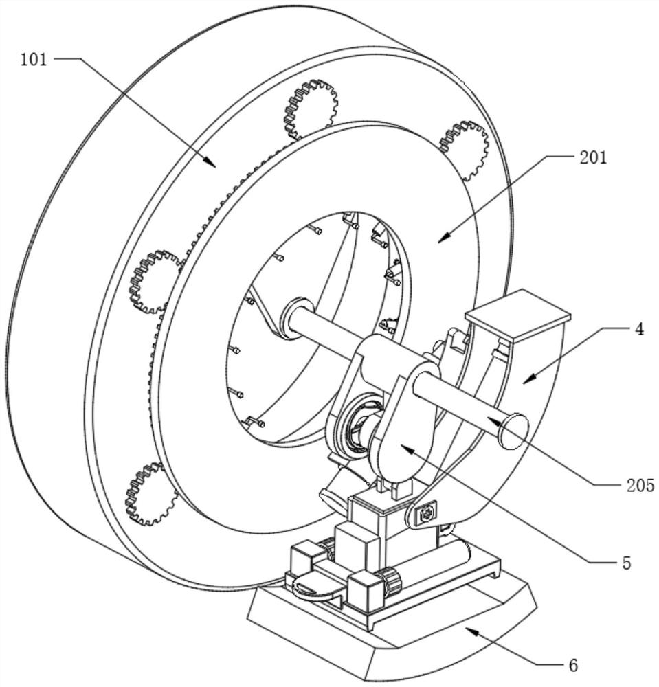
[0040] Refer to the attached figure 2 and image 3 , the adjustment base frame 2 also includes a ring plate frame 201, the center of the two ring plate frames 201 is fixedly provided with a center frame 204, and the two ring plate frames 201 are fixedly installed with roller columns 205 through the center frame 204. One side of the frame 201 close to the ring support frame 101 is fixedly provided with an inner insertion frame 202, and the inner insertion frame 20...
Embodiment 2
[0047] Refer to the attached Image 6 , the safety mechanism 5 also includes a safety tube 501, the safety tube 501 is movably sleeved on the outer surface of the roller column 205, a tube frame 502 is fixedly arranged on one side of the outer wall of the safety tube 501, and an inner rod 503 is slidably installed inside the tube frame 502, The second motor 403 is fixed with a swivel base 504 toward the center of the circle, and one end of the inner rod 503 is rotatably connected to the swivel base 504. During the process of transporting the segment 6, the angle and position of the second motor 403 change anytime and anywhere.
[0048] Refer to the attached Image 6 , the inner side of the pipe frame 502 is rotated to install the side rotating rod, the outer surface of the side rotating rod is fixedly sleeved with a second gear 506, and one side wall of the inner rod 503 is fixedly provided with a straight row of teeth 505. The straight row of teeth 505 and the second gear 50...
Embodiment 3
[0053] Refer to the attached Figure 8 , the dust collector 7 also includes a working shell 701, the working shell 701 is fixedly installed on the side wall of the ring plate frame 201, one side of the working shell 701 is rotatably installed with a fitting wheel 702, and the fitting wheel 702 and the ring support The inner surfaces of the frame 101 are abutted against each other. During the rotation of the ring plate frame 201 , the fitting wheel 702 will roll against the inner surface of the ring support frame 101 .
[0054] Refer to the attached Figure 9 One end of the working housing 701 is rotatably installed with a crankshaft 706, the crankshaft 706 is fixedly connected with the fitting wheel 702, the end of the crankshaft 706 is rotatably connected with a deflection rod 707, and the end of the deflection rod 707 is rotatably connected with a piston 708, and the piston 708 is slidably installed Inside the working casing 701, the fitting wheel 702 will drive the cranksh...
PUM
 Abstract
Description
Claims
Application Information
 - R&D
- Intellectual Property
- Life Sciences
- Materials
- Tech Scout
- Unparalleled Data Quality
- Higher Quality Content
- 60% Fewer Hallucinations
Browse by: Latest US Patents, China's latest patents, Technical Efficacy Thesaurus, Application Domain, Technology Topic, Popular Technical Reports.
© 2025 PatSnap. All rights reserved.Legal|Privacy policy|Modern Slavery Act Transparency Statement|Sitemap|About US| Contact US: help@patsnap.com


