
Patsnap Eureka
For R&D, Patsnap Eureka makes reading and utilizing patents & technical documents easy.
Patsnap Eureka AIR
Designed for self-driven R&D workflows. Generate viable solutions, solve complex R&D challenges, empower your innovation with AI.

Patsnap Eureka Materials
Designed for material experts only. Revolutionize your material R&D, from search, analyze, to developing new materials.

TechResearch
Generate reliable direction feasibility study reports for your R&D in just a few steps.

TechSeek
Discover and master advanced knowledge NOW. Basics, ideas, possibilities, all at once.

TechMind
As an expert in R&D Theories, TechMind can generates customized viable solutions instantly.

TechRisk
Analyze your overall solution with one click, know your potential R&D risks in advance.

TechMonitor
Get weekly tech updates, stay abreast of the latest tech innovations and key insights.
Through-flow turbine device with bent groove
A technology of tubular water turbines and curved grooves, applied in the direction of reaction engines, mechanical equipment, hydroelectric power generation, etc., can solve the problems affecting the overall efficiency of water turbines, increase the maintenance cost of water turbines, and affect the stable operation of units, so as to solve the blade tip clearance Effects of cavitation, solution to pressure pulsation, and reduction of green strength
- Summary
- Abstract
- Description
- Claims
- Application Information
AI Technical Summary
Problems solved by technology
Method used
Image

Examples
Embodiment Construction
[0017] The present invention will be described in detail below with reference to the accompanying drawings and specific embodiments.
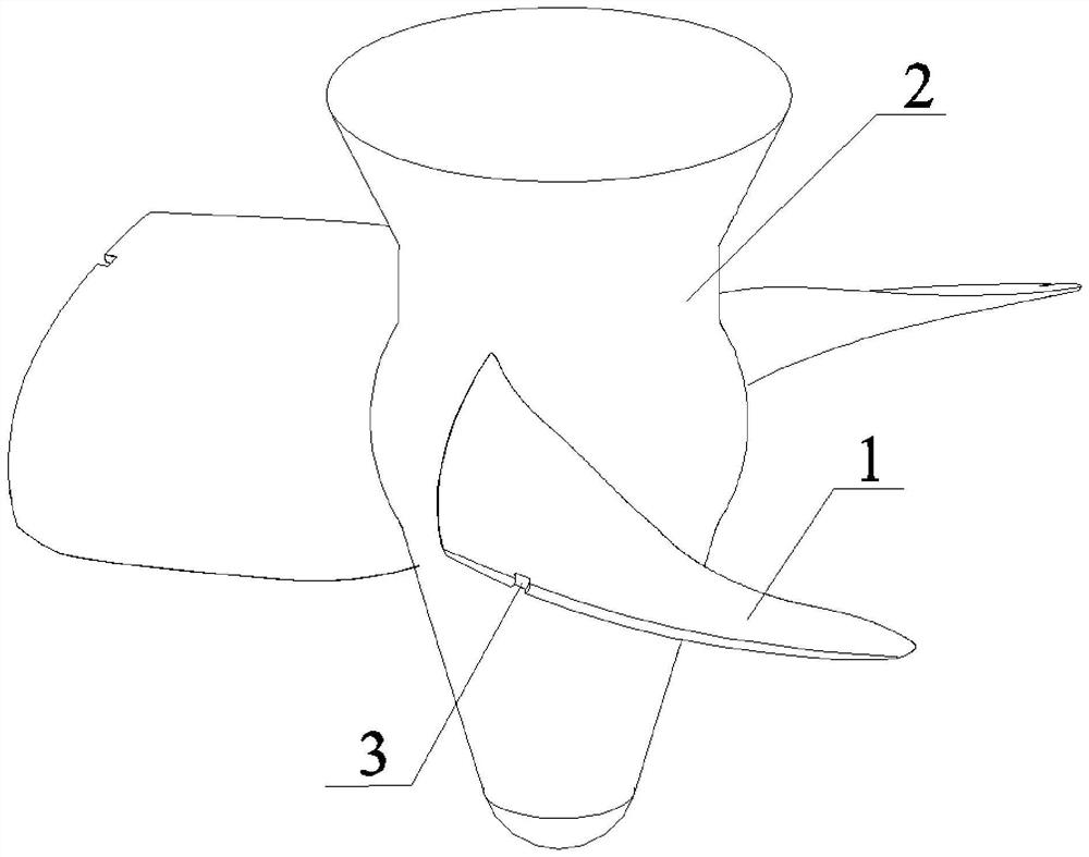
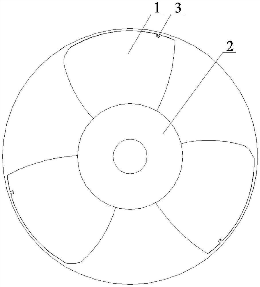
[0018] The tubular water turbine device with curved grooves of the present invention has a structure as follows: Figure 1-2 As shown, it includes a hub 2, the outer wall of the hub 2 is fixed with a plurality of blades 1 along its circumferential direction, the surface of each blade 1 is provided with a curved groove 3, and the curved groove 3 is arranged in the gap between the blade 1 and the inner wall of the runner. On the side, the curved groove 3 is opened on the edge of the blade 1 .
[0019] The blade 1 has a pressure surface and a suction surface. Under the condition that the rest of the geometry is kept unchanged, a curved groove 3 is made to pass through the pressure surface and the suction surface on the edge of the blade 1 at the gap position.
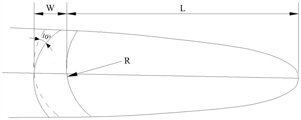
[0020] The right profile line of the curved groove 3 is set at a position 15% of the c...
PUM
 Abstract
Description
Claims
Application Information
 - R&D Engineer
- R&D Manager
- IP Professional
- Industry Leading Data Capabilities
- Powerful AI technology
- Patent DNA Extraction
Browse by: Latest US Patents, China's latest patents, Technical Efficacy Thesaurus, Application Domain, Technology Topic, Popular Technical Reports.
© 2024 PatSnap. All rights reserved.Legal|Privacy policy|Modern Slavery Act Transparency Statement|Sitemap|About US| Contact US: help@patsnap.com