Low-vibration vortex pump volute

A swirl pump, low-vibration technology, applied in pumps, components of pumping devices for elastic fluids, pump elements, etc., to achieve uniform pressure distribution, reduce energy loss, and reduce velocity gradients

Pending Publication Date: 2022-08-09
JIANGSU UNIV ZHENJIANG RES INST OF FLUID ENG EQUIP TECH +1
View PDF6 Cites 0 Cited by
  • Summary
  • Abstract
  • Description
  • Claims
  • Application Information

AI Technical Summary

Problems solved by technology

[0005] The invention solves the vibration problem caused by the static and dynamic interference between the impeller and the pump body in the prior art by providing a low-vibration swirl pump volute, improves the vibration phenomenon during the operation of the swirl pump and improves the performance of the swirl pump to a certain extent. Hydraulic performance of swirl pump

Method used


Image

  • Low-vibration vortex pump volute
  • Low-vibration vortex pump volute
  • Low-vibration vortex pump volute

Examples


Embodiment 1

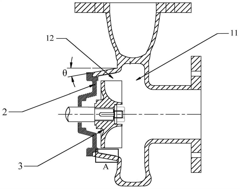
[0026] like figure 1 A schematic structural diagram of the low-vibration swirl pump volute provided by the present invention is illustrated.

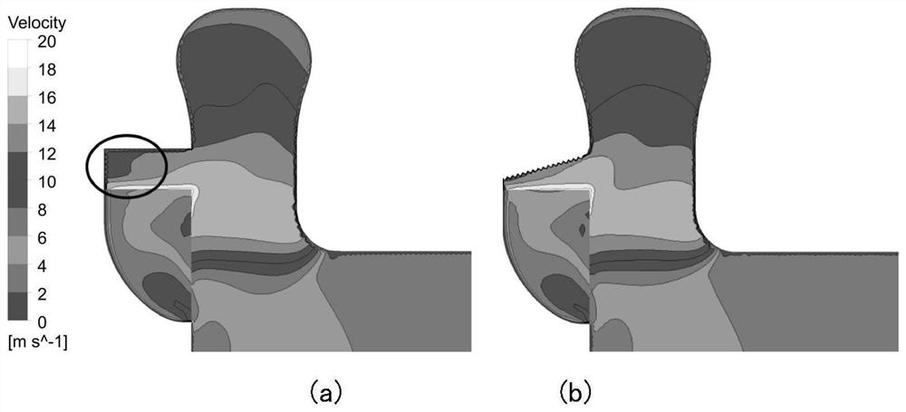
[0027] exist figure 1 , the frontal section of the structure of the low-vibration swirl pump volute is provided, and the swirl pump volute may include: a front pump body 11 and a retraction cavity 12 , the front pump body 11 and the retraction cavity 12 are integrated structure; a groove is provided on the inner wall surface of the retraction cavity 12, and the wall surface of the retraction cavity 12 has an inclination angle θ compared to the axis of the volute of the swirl pump;

[0028] The front pump body 11 is used to reduce the speed of liquid flow, so that the speed corresponding to the speed can be converted into pressure energy;

[0029] The setback cavity 12 is used for placing the impeller 3 , increasing the axial distance between the impeller 3 and the inlet of the setback cavity 12 .

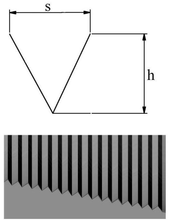
[0030] Optionally, V-shaped grooves...


PUM


Abstract

The invention belongs to the technical field of fluid machinery, and relates to a low-vibration vortex pump volute. The invention discloses a low-vibration vortex pump volute which comprises a front pump body and a rear shrinkage cavity, and the front pump body and the rear shrinkage cavity are of an integrated structure. A groove is formed in the inner wall face of the rear shrinkage cavity, and the wall face of the rear shrinkage cavity has an inclined angle relative to the axis of the vortex pump volute. The front pump body is used for reducing the flowing speed of liquid, so that speed energy corresponding to the speed is converted into pressure energy; the rear shrinkage cavity is used for containing an impeller, and the axial distance between the impeller and an inlet of the rear shrinkage cavity is increased. The flow state of an outlet of the vortex pump can be improved, dynamic and static interference between the impeller and the volute can be reduced, and finally the vibration phenomenon during operation of the vortex pump can be improved.

Description

technical field [0001] The invention relates to the technical field of fluid machinery, in particular to a low-vibration swirl pump volute. Background technique [0002] The impeller of the cyclone pump completely retreats into the retracted cavity, and there is a large axial space between the impeller and the inlet of the pump body, which has excellent non-clogging performance. Therefore, the cyclone pump is widely used in materials containing fibers, mud, minerals Transport scenarios of complex media such as particles. [0003] Due to the small gap between the outlet of the impeller of the swirl pump and the shell wall of the retraction cavity, the dynamic and static interference is strong, which leads to poor vibration and noise performance. Furthermore, when the swirl pump is working, a through flow and a circulating flow are formed in the bladeless cavity. Due to the existence of the circulating flow, a large hydraulic loss is caused, and the efficiency of the pump is ...

Claims


Application Information

Patent Timeline
Patent Type & Authority Applications(China)
IPC IPC(8): F04D29/40F04D29/66
CPCF04D29/406F04D29/669Y02E10/20
Inventor 谈明高赵凯尧吴贤芳刘厚林王勇王凯董亮
Owner JIANGSU UNIV ZHENJIANG RES INST OF FLUID ENG EQUIP TECH
Why Eureka
Try Eureka