
Device for short-circuit protection

A technology of short-circuit protection and short-circuit current, which is applied to emergency protection devices, circuit devices, emergency protection circuit devices, etc., and can solve problems such as not being able to switch to contactors immediately

Inactive Publication Date: 2004-05-05
SIEMENS AG
View PDF3 Cites 0 Cited by
  • Summary
  • Abstract
  • Description
  • Claims
  • Application Information

AI Technical Summary

Problems solved by technology

[0008] However, this method cannot be immediately transferred to contactors with higher rated current (100-400A)

Method used


Image

  • Device for short-circuit protection
  • Device for short-circuit protection
  • Device for short-circuit protection

Examples


Embodiment Construction

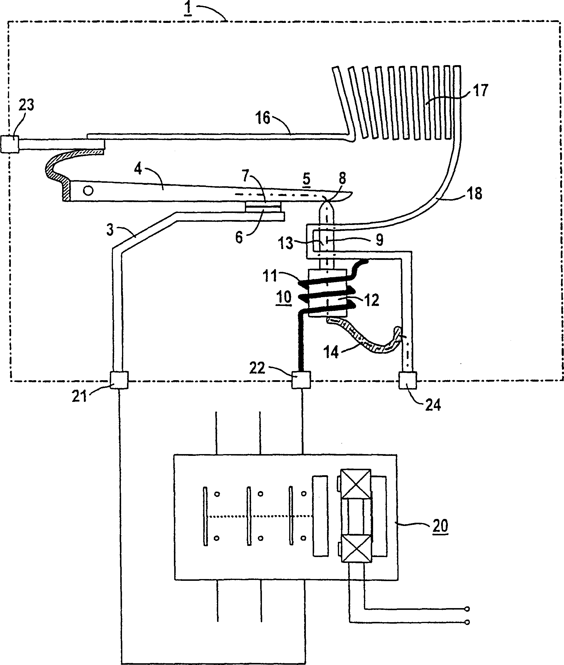
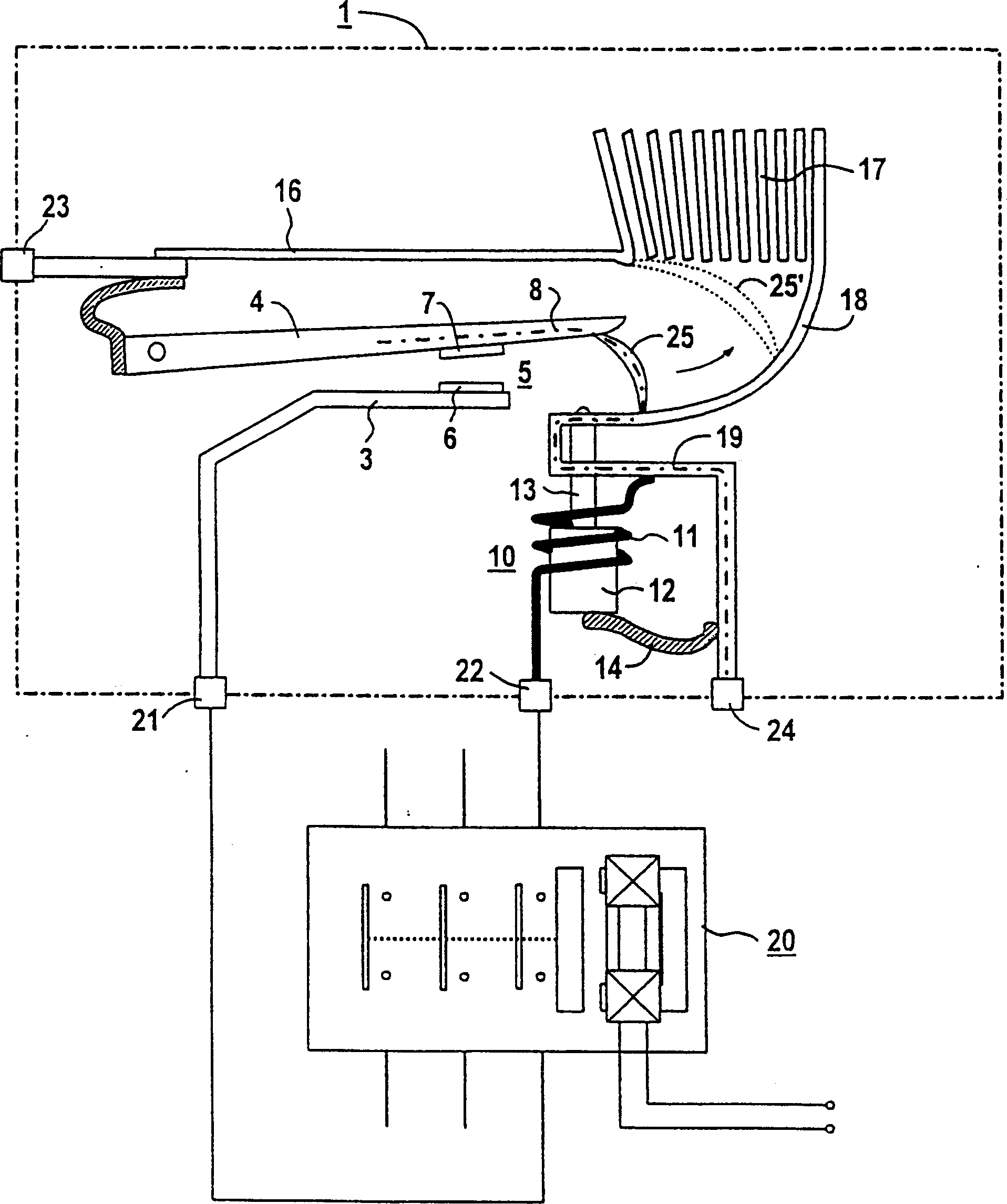
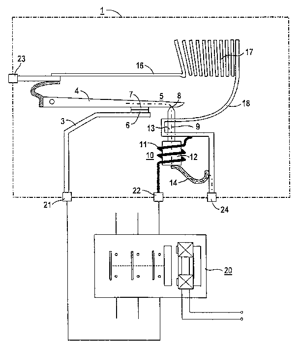
[0020] Typical switching components, such as switch locks and overcurrent releases, are not shown in detail in the drawings. It is assumed that the contactor is equipped with a non-weldable contact material so that the contact material will not fuse under certain arc loads. Furthermore, apart from the forces caused by the short-circuit current or by the elastic store, no external energy, such as electrical auxiliary energy or chemical energy, needs to be used to achieve the short-circuit protection.

[0021] A current limiting device 1 for preventing contact welding consists of a current limiting switch with a short-circuit mechanism and a contactor 20 with a magnetic drive. The short-circuit mechanism comprises a first short-circuit current branch 9 with a short-circuit contact 8 and a second short-circuit current branch 19, wherein the first short-circuit current branch 9 is connected by a magnetic release 10, and the second short-circuit current branch 9 is connected by a m...


PUM


Abstract

A power limiting mechanism must be provided especially for protecting electrical-mechanical contactors from welding during power surge resulting from a short circuit. According to the invention, the power limiting mechanism (1) closes a short-circuiting contact (8) of a first short-circuiting branch circuit (9) to disconnect the contactor (20) during a first step and the short-circuiting function thereof is then carried out by an arc (25, 25') having a second short-circuiting branch circuit (19) in a second step. During the disconnection process, the arc is commuted by the short-circuiting contact (8) on the associated conducting bars (16, 18) and flows into an arcing chamber (17) of the power-limiting mechanism, whereby the short circuit is interrupted.

Description

technical field [0001] The invention relates to a short-circuit protection device for an electromechanical contactor, especially for preventing welding of contacts of the contactor under short-circuit load, wherein a current limiting mechanism is provided. Background technique [0002] DE 4040359 C2 and DE 4110335 C2 already know a flow limiting device for at least a temporal conduction. Furthermore, a device is known from EP 0691 046 B1 for disconnecting a branch of a low-voltage line network in the event of a short circuit, whereby, in the branch, consumers are connected to the phase conductor and an associated neutral conductor , and a switching element for switching on and / or disconnecting is connected in series in front of this or these electrical appliances, and an additional switching element for cutting off a short circuit is provided in the phase line and / or neutral line, one with The short-circuit circuit of the switch is connected to these additional switching el...

Claims


Application Information

Patent Timeline
Patent Type & Authority Patents(China)
IPC IPC(8): H01H9/38H01H9/42H01H50/00H01H73/00H01H73/18H01H89/06H02H3/02H02H7/22
CPCH02H3/023H01H2089/065H02H7/222H01H89/06
Inventor 弗里茨·波尔
Owner SIEMENS AG
Learn More