Phase shifted H-Bridge resonant converter with symmetrical currents

a phase shift and symmetrical current technology, applied in the field of design, can solve the problems of not producing symmetrical currents, limiting peak currents, and circuits that have not shown to correct, and achieve the effect of reducing the power requirement of ac load circuits

Inactive Publication Date: 2009-02-19
SMITH STEPHEN WILLIAM
View PDF6 Cites 37 Cited by
  • Summary
  • Abstract
  • Description
  • Claims
  • Application Information

AI Technical Summary

Benefits of technology

[0007]An object of this invention is to prevent the peak currents from exceeding the switching devices ratings.
[0010]Furthermore, introducing a “loosely” coupled inductor controls the maximum symmetrical current in the H-bridge in open, short or under load conditions. This reduces the need for high power switching devices, and complex protection control circuits that add to the cost.
[0011]The final object of this invention is to demonstrate that the introduction of a “loosely” coupled inductor reduces the AC load circuit power requirement as it balances the recycled power from the resonant tank circuit of the H-bridge.

Problems solved by technology

These circuits have not shown to correct, in a “passive manner,” the limiting of peak currents in the switching devices.
In addition, they do not produce symmetrical currents.
However, controlling the current in the converters with an active current protection scheme does not always result in protecting the switching devices from failures.
This can exacerbate the failure of the active protection scheme.
The historical problems with these power conversion topologies are that the operation of H-Bridge resonant circuits can be compromised in open or short circuit conditions.
When the H-Bridge is operated without symmetrical switch currents and peak current limitations, the peak voltages and currents through the H-Bridge switches can be excessive.
This often results in switch failure.

Method used


Image

  • Phase shifted H-Bridge resonant converter with symmetrical currents
  • Phase shifted H-Bridge resonant converter with symmetrical currents
  • Phase shifted H-Bridge resonant converter with symmetrical currents

Examples


Embodiment Construction

[0019]While specific embodiments of the invention have been shown and described in detail to illustrate the specific application of the principals of the invention, it will be understood that the invention may be embodied as fully described in the claims, or as otherwise understood by those skilled in the art, without departing from such principals.

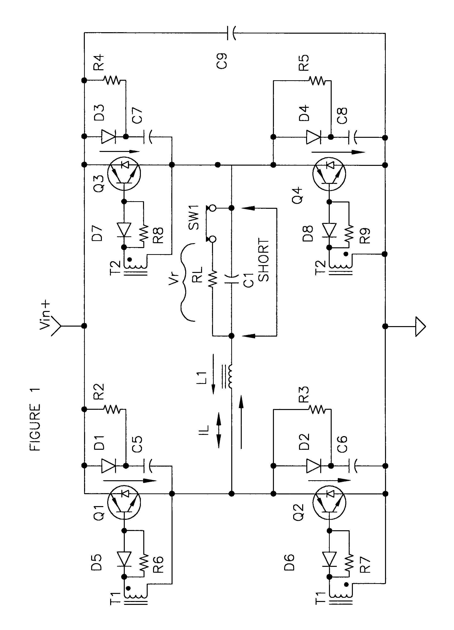
[0020]FIG. 1 is a circuit diagram of a parallel loaded H-Bridge resonant converter according to prior art. RL represents a load, which is equivalent to a transformer rectifier output. The converter operates at a constant switching frequency and is controlled by gate signals applied to Q1-Q4. As seen in the figure, the resonant tank circuit is comprised of L1, C1, and R1. “SW1” represents an open or a shorted load condition across C1. An input DC voltage, V+ is converted to an output voltage Vr and output current Ir, which in turn is applied to RL.

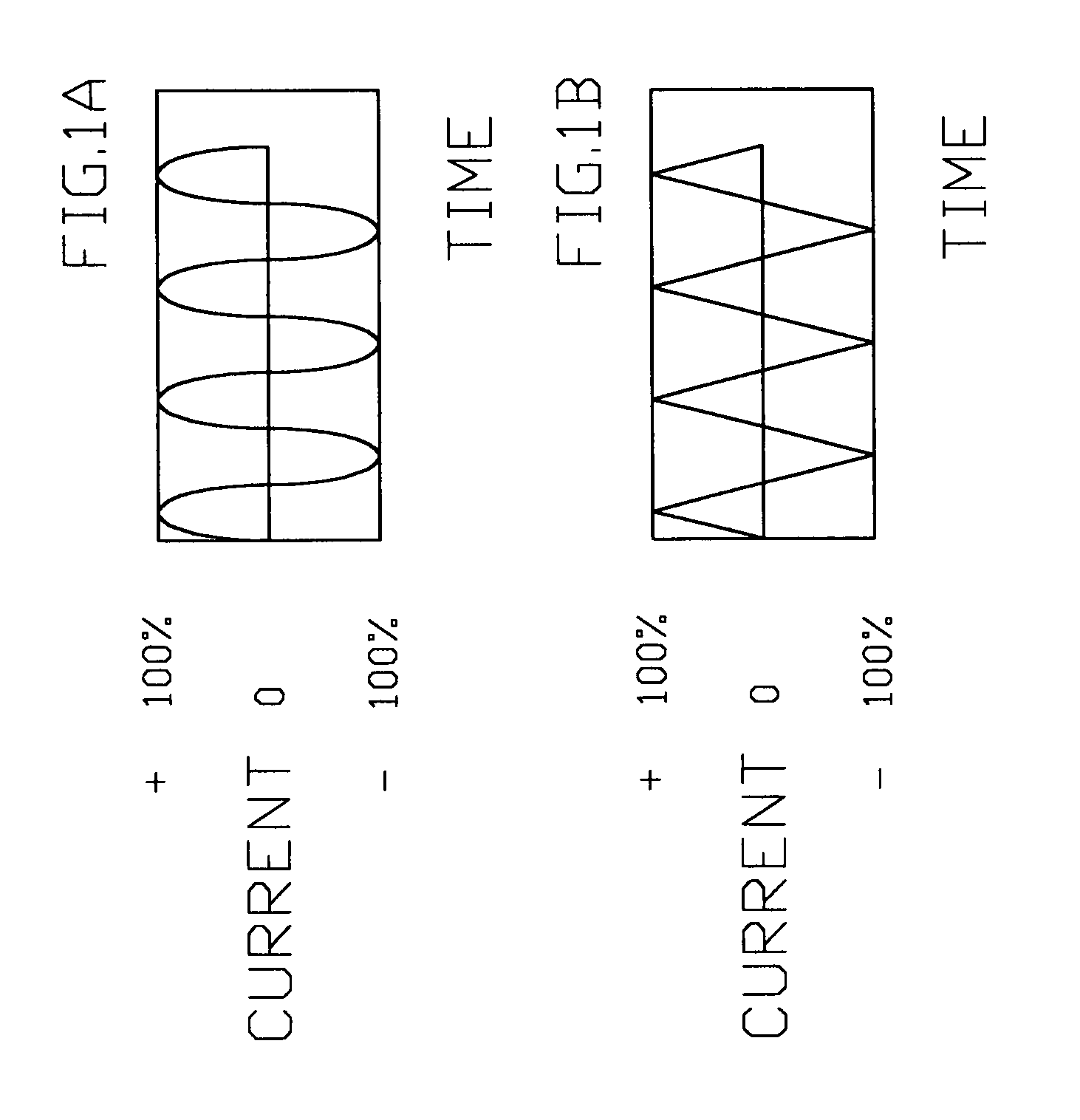
[0021]FIG. 1A is the current IL through RL under normal load conditions, with SW1 closed. The...


PUM


Abstract

An H-bridge, phase shifted resonant converter, with symmetrical switched currents is described. This includes open and short circuit protection, with phase shift operation to zero output. The proposed circuit includes an H-bridge converter, employing the use of a “loosely” coupled inductor in place of the standard series inductor(s) to reduce the peak currents. In addition, the current will be symmetrical in all of the H-bridge switching devices. Furthermore, the impedance of the “loosely” coupled inductor controls the maximum current in the H-bridge in an open, short, or under load conditions. The “loosely” coupled inductor, with the addition of a small AC load, enhances the operation of the converter near zero output.The control circuit of the H-bridge converter can be modulated to completely shut off the output without the introduction of complex circuitry.

Description

TECHNICAL FIELD AND INDUSTRIAL APPLICABILITY OF THE INVENTION[0001]This invention relates to the design of H-Bridge phase-shifted resonant converter. This present invention relates in particular to the operation of the converter in over-load, load, and no-load conditions. The invention reduces stress and potential failures of the devices in the H-Bridge phase-shifted resonant converters.BACKGROUND OF THE INVENTION[0002]Most dc-to-dc converters employing H-Bridge topologies achieve the conversion of a primary dc voltage input to an output regulated dc voltage. Typically, the dc input voltage is converted to an ac voltage (or pulses) by switching devices (transistor, mosfet, insulated gate bipolar transistor or thyristor). The ac voltage is then converted to a regulated dc output voltage. By controlling the duty cycle or the frequency of the ac voltage (or pulses), the desired output voltage or output current regulation can be achieved. These methods of controlling the output are typi...

Claims


Application Information

Patent Timeline
Patent Type & Authority Applications(United States)
IPC IPC(8): H02M3/335
CPCY02B70/1433H02M3/33569Y02B70/10H02M3/33573H02M3/01
Inventor SMITH, STEPHEN WILLIAM
Owner SMITH STEPHEN WILLIAM
Why Eureka
Try Eureka