Method and apparatus for preventing fraudulent access in conditional access system

A conditional access and fraudulent technology, applied in the direction of collaborative devices, TV system components, error prevention, etc., to achieve the effect of preventing fraudulent access

Inactive Publication Date: 2004-06-09
CANAL SOCIETE ANONYME
View PDF0 Cites 0 Cited by
  • Summary
  • Abstract
  • Description
  • Claims
  • Application Information

AI Technical Summary

Problems solved by technology

[0004] In the existing broadcasting system, the user uses the smart card to obtain the receiving authority, but there is a problem of preventing the abuse of the card to defraud the owner of the authority

Method used


Image

  • Method and apparatus for preventing fraudulent access in conditional access system
  • Method and apparatus for preventing fraudulent access in conditional access system
  • Method and apparatus for preventing fraudulent access in conditional access system

Examples


Embodiment Construction

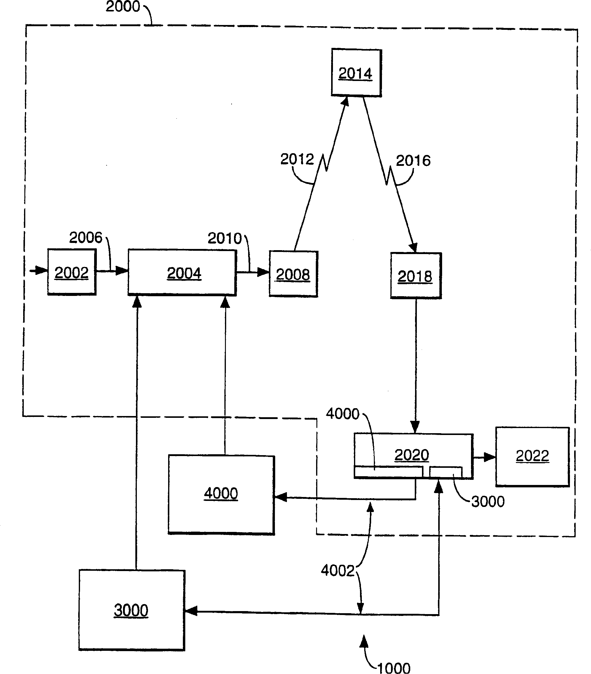
[0043] figure 1 A digital broadcasting and receiving system 1000 is shown which includes a conventional digital television system 2000 which uses the known MPEG-2 compression system to transmit compressed digital signals. An MPEG-2 compressor 2002 located in a broadcast center receives a digital signal stream (usually a video signal stream). Compressor 2002 is connected to multiplexer and encryptor 2004 by line 2006 . Multiplexer 2004 receives a number of additional input signals, assembles one or more transport streams, and transmits the compressed digital signal to broadcast center transmitter 2008 via link 2010, which may of course take many forms, including telecommunications link. Transmitter 2008 transmits electromagnetic signals via uplink 2012 to satellite transponder 2014 where they are electronically processed and broadcast via abstracted downlink 2016 to ground receiver / decoder 2018, typically owned or leased by the end user dish antenna. Signals received by rec...


PUM


Abstract

A receiver/decoder is programmed only to accept a current entitlement control message (EMM) if it has received at least a previous EMM of a previous calendar period. When this is received, it is used to check present rights in the receiver/decoder. The invention prevents an original subscriber from fraudulently obtaining rights by disconnecting a decoder (before an authorising message can update the decoder's memory to prevent decryption) and by reconnecting the decoder (so as to be mistaken for a new subscriber legitimately having those rights).

Description

technical field [0001] The present invention relates to a method and arrangement for preventing fraudulent access to a conditional access system connected to a user receiver / decoder. This technique can be used in the field of data communications, where transmitted encrypted data is received and decoded, for example, by an authorized user receiver / decoder. Background technique [0002] The term "receiver / decoder" as used herein refers to a receiver for receiving encoded or unencoded signals, such as television and / or radio signals. The term can also refer to a decoder used to decode a received signal. Embodiments of such a receiver / decoder may include a decoder integrated with the receiver, such as in a "set-top box" for decoding received signals, or used in conjunction with a physically separate receiver decoder. [0003] Reference above to the receiver / decoder being "connected to" the conditional access system includes the possibility that the receiver / decoder either for...

Claims


Application Information

Patent Timeline
Patent Type & Authority Patents(China)
IPC IPC(8): G06F9/445G06F9/06G06F9/46G06F9/48G06F11/00G06F11/08G06F11/10G06F11/14G06F11/26G06F11/28G06F12/00G06F12/02G06F13/00G06F13/10G06K17/00G06K19/00G06K19/07G06T9/00G07F7/00G07F7/02G07F7/08G07F7/10G09C1/00G11C8/06G11C16/02H04B1/713H04H20/02H04H40/00H04L1/00H04L9/10H04L9/32H04L12/56H04L13/08H04L29/10H04NH04N5/222H04N5/455H04N7/14H04N7/26H04N7/66H04N17/00H04N17/04H04N21/4367H04N21/442H04N21/462H04N21/4623H04N21/4627H04N21/6334H04N21/8355
CPCH04N7/17318H04N21/258H04N7/16G07F7/1008H04N21/8166H04N7/1675H04N7/17309G06Q20/342G06Q20/04G11C16/105H04N21/4437G07F7/08G06Q20/4033G07F7/025H04N17/004G06F11/1435H04N21/8355H04N21/4627H04N21/4367G06Q20/06H04N7/163H04N21/4623H04N7/167H04N21/4782H04N21/4622H04N5/4401G06Q20/341G06T9/007G06F9/4843H04N21/6334G06Q20/40975G06Q20/1235H04N21/44236G06F11/10G07F17/0014H04N21/426
Inventor M·梅拉德
Owner CANAL SOCIETE ANONYME
Why Eureka
Try Eureka