Light emitting container for high-pressure discharge lamp and manufacturing method thereof

A technology of high pressure discharge lamps and manufacturing methods, which is applied in the manufacture of discharge tubes/lamps, components of gas discharge lamps, and electrode systems, and can solve problems such as uneven wall thickness of light-emitting containers, achieve high transmittance, improve Excellent mechanical strength and efficiency

Inactive Publication Date: 2004-06-30
NGK INSULATORS LTD
View PDF2 Cites 0 Cited by
  • Summary
  • Abstract
  • Description
  • Claims
  • Application Information

AI Technical Summary

Problems solved by technology

[0008] In this case, as long as the diameter of the opening part 7 can be ensured to remove the remaining paste, although its diameter can be made below 2 mm (however, it must be above 0.8), but from the characteristics of casting molding, It is not possible to manufacture a luminous vessel with an uneven wall thickness as a whole in which at least the central part of the torso is thinner than the end parts and the junction area between the end parts and the torso

Method used


Image

  • Light emitting container for high-pressure discharge lamp and manufacturing method thereof
  • Light emitting container for high-pressure discharge lamp and manufacturing method thereof
  • Light emitting container for high-pressure discharge lamp and manufacturing method thereof

Examples


Embodiment Construction

[0036] The light-emitting container and its manufacturing method of the present invention will be described in detail with reference to the drawings.

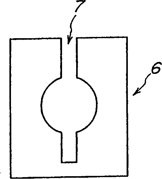
[0037] image 3 It is a cross-sectional view of an embodiment of the light-emitting container of the present invention. The luminescent vessel includes a substantially spherical body 1 forming a discharge space and end portions 2a, 2b into which electrode members are inserted, which are integrally formed of alumina as a light-transmitting ceramic material.

[0038] In this embodiment, the outer diameter A, inner diameter a and axial length B of the torso 1 are respectively set at 2-30 mm, 1-15 mm and 2-50 mm.

[0039] The end portions 2a, 2b each have an axial length L of 10-20 mm and an inner diameter d of 0.5-2.5 mm. Therefore, the ratio of the length L to the inner diameter d is 4-40. The reason why the ratio of the length L to the inner diameter d is set to such a value is that this value is suitable.

[0040] The wall...


PUM


Abstract

A light emitting container comprising a trunk unit for forming a discharge space and a terminal unit into which an electrode member is inserted, both units being integrally formed from a transparent ceramic material, wherein at least the middle region of the trunk unit is smaller in wall thickness than the terminal unit and the boundary region between the terminal unit and the trunk unit and the inner diameter of the terminal unit is about 2 mm or smaller.

Description

technical field [0001] The present invention relates to a light-emitting container for a high-pressure discharge lamp and a manufacturing method thereof. [0002] Furthermore, the invention relates to a high-pressure discharge lamp having such a luminous vessel and a method for its production. Background technique [0003] As such a light-emitting container, there is a light-emitting container in which a trunk forming a discharge space and an end portion inserted into an electrode member are integrated (hereinafter referred to as an “integrated light-emitting container”), and a body and an end portion are formed as separate members, and then A light-emitting container that assembles them (hereinafter referred to as an "assembled light-emitting container"). In the case of an assembled light-emitting container, although the end part is inserted into the opening part of the trunk, the efficiency of the bulb will be reduced due to the heat loss of these joint parts, so it canno...

Claims


Application Information

Patent Timeline
Patent Type & Authority Patents(China)
IPC IPC(8): H01J9/26H01J61/30
CPCH01J9/266H01J61/30
Inventor 宫泽杉夫浅井道生
Owner NGK INSULATORS LTD
Why Eureka
Try Eureka