
Controllable inductor

An inductor, a technology for controlling current, used in variable inductors, inductors, variable transformers, etc.

Inactive Publication Date: 2004-07-07
ABB (SCHWEIZ) AG
View PDF1 Cites 0 Cited by
  • Summary
  • Abstract
  • Description
  • Claims
  • Application Information

AI Technical Summary

Problems solved by technology

A disadvantage of this known controllable inductor is that the alternating voltage in the main winding induces in the control winding an alternating voltage with twice the fundamental frequency in the main winding

Method used


Image

  • Controllable inductor
  • Controllable inductor
  • Controllable inductor

Examples


Embodiment Construction

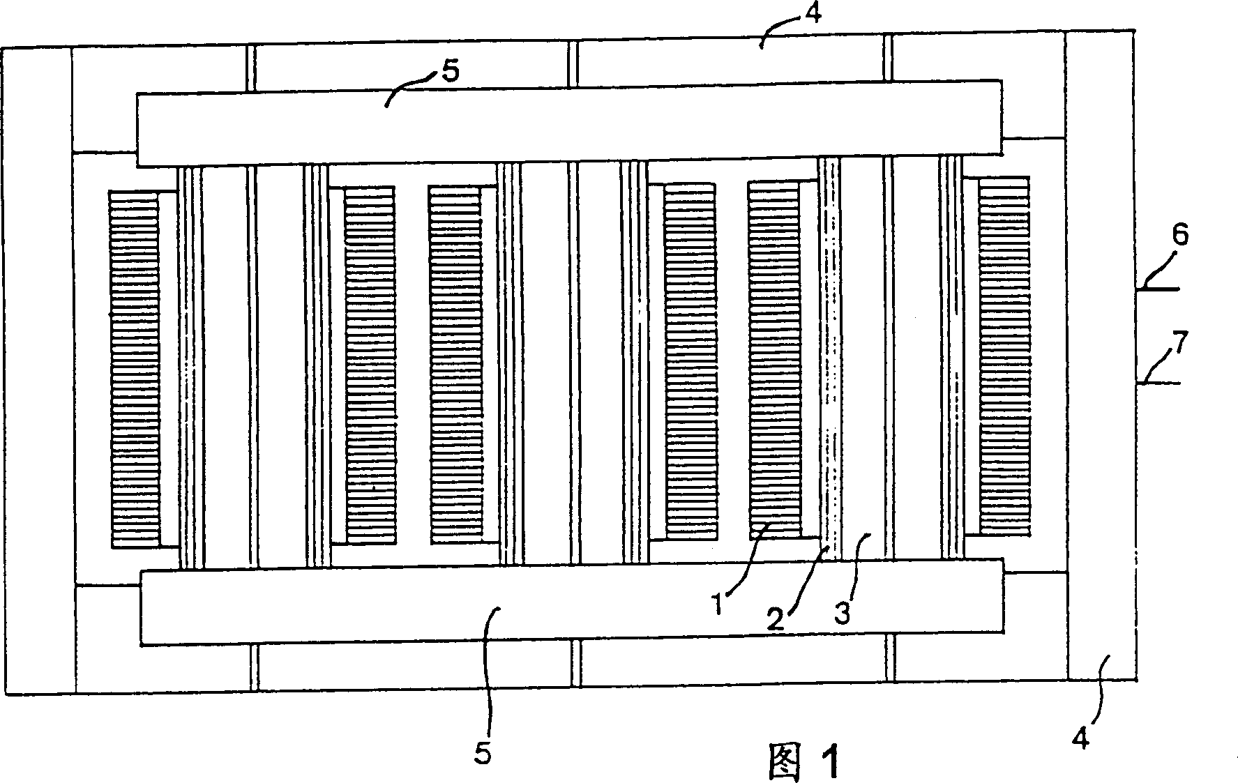
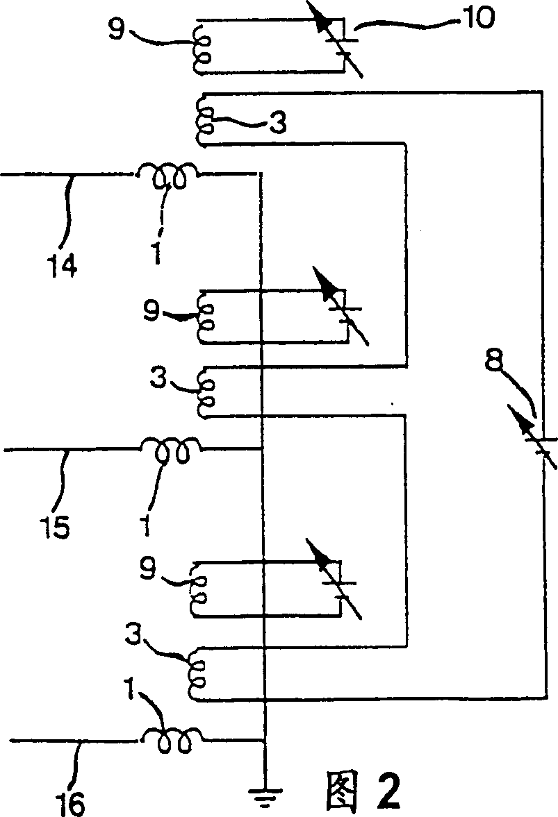
[0021] Fig. 1 illustrates the connection of an inductor according to the invention having a control winding each core connected in series in a three-phase AC circuit. The inductor has a main winding 1, a core 2 arranged substantially coaxially with the main winding and a control winding 3 extending axially through the core for each phase of a three-phase network. In this way, each main winding 1 is connected in series in one phase of the AC network and has an upper end at high potential, the voltage falling towards the lower end in FIG. 1 , which may or may not be at ground potential. The control windings 3 are connected in series with each other and extend symmetrically between them by means of a part 4, said part 4 and the part of the control winding extending through the core are made of plate material with high electrical conductivity, for example copper plate, in the form of this plate structure The control winding has a stable mechanical structure and is able to guide th...


PUM


Abstract

A controllable inductor comprises at least a tubular core, a main winding (1) surrounding the core and a control winding (3) passing substantially axially through the core. It is adapted for connection to a three phase alternating current network and has for this sake for each phase (14-16) a main winding (1) for connection to the phase, a core and a control winding, and the control windings of the three phases are electrically connected in series to each other.

Description

technical field [0001] The invention relates to a controllable inductor comprising at least a tubular core, a main winding surrounding the core and a control winding passing substantially axially through said core. technical background [0002] This controllable inductor can be connected to any circuit, such as a power line, through its main winding, so as to provide inductance for the circuit, for example, to eliminate high-order harmonic current generated in the circuit. The magnetic permeability of the core and thus the inductance of the inductor can be controlled by varying the control current axially through the core within said control winding. By connecting such a controllable inductor and capacitor in series a so-called harmonic filter can be obtained, which is already known, for example, from the applicant's WO94 / 11891 patent application, wherein by controlling the inductance of the inductor, for certain frequencies the The impedance is controlled to a low value, t...

Claims


Application Information

Patent Timeline
Patent Type & Authority Patents(China)
IPC IPC(8): H01F29/14
CPCH01F2029/143H01F29/14
Inventor S·瓦尔德马松L·利尔杰斯特兰
Owner ABB (SCHWEIZ) AG
Learn More