Sealing device for axial flow turbine

A technology for axial flow turbines and sealing devices, which is applied to the sealing of engines, gas turbine devices, jet propulsion devices, etc.

Inactive Publication Date: 2004-08-04
KK TOSHIBA
View PDF1 Cites 0 Cited by
  • Summary
  • Abstract
  • Description
  • Claims
  • Application Information

AI Technical Summary

Problems solved by technology

Therefore, this axial turbine cann...

Method used


Image

  • Sealing device for axial flow turbine
  • Sealing device for axial flow turbine
  • Sealing device for axial flow turbine

Examples


Embodiment Construction

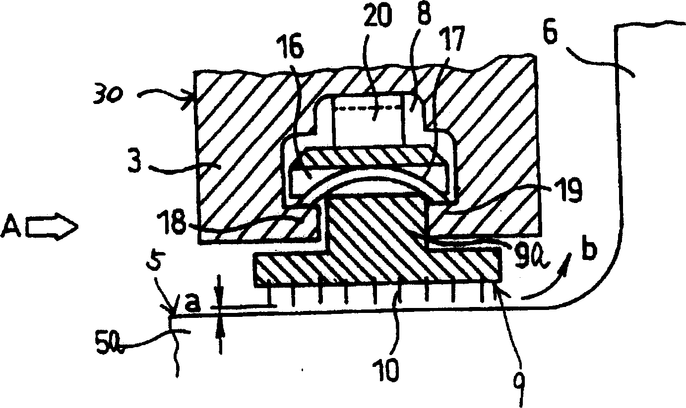
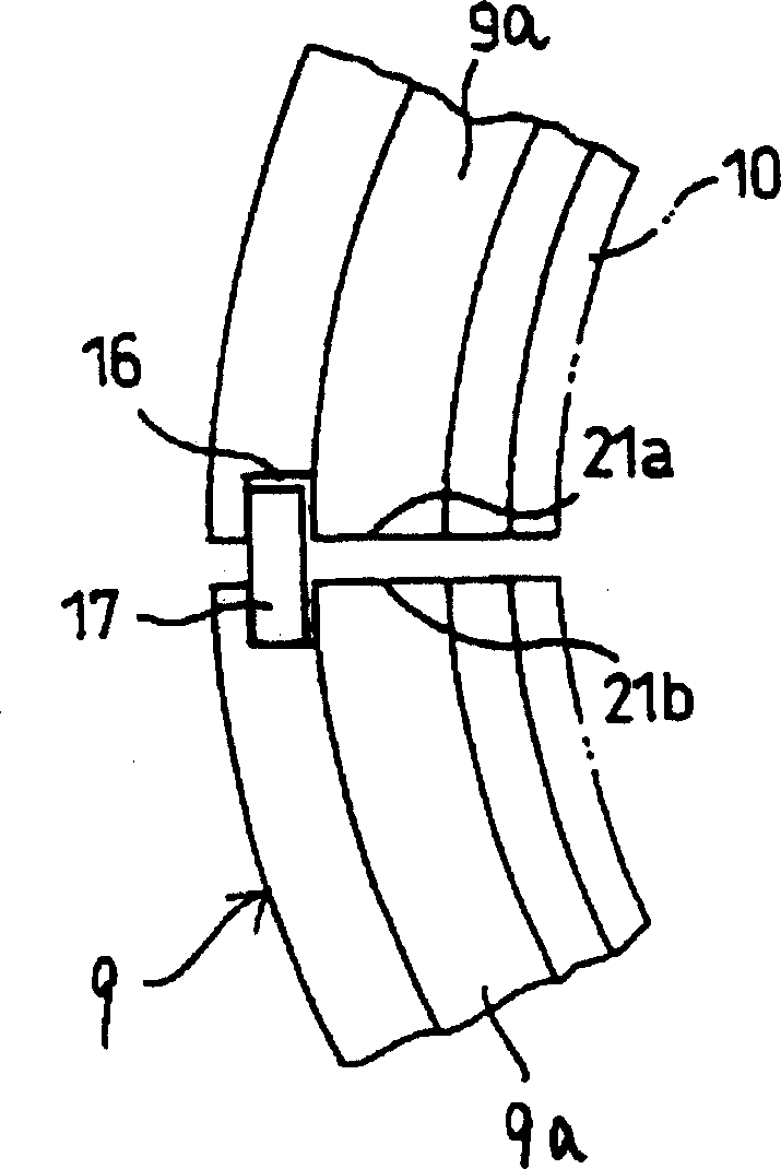
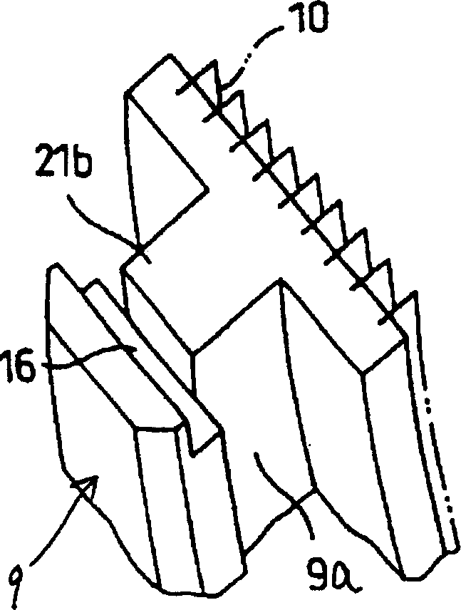
[0052] Next, a sealing device according to a first embodiment of the present invention will be described. The same components as those in the prior art are denoted by the same reference numerals and their descriptions can be omitted. From Figure 1A It can be seen that there is a placement groove 8 on the inner peripheral surface of an inner ring 3 of a nozzle partition 30 , a plurality of sectors 9 a of a sealing ring 9 are distributed along the circumference, and its outer wall is placed in the placement groove 8 . The sealing fins 10 are fixedly installed on the inner surface of the sector body 9a facing the rotor 5 of the axial flow turbine. A gap a is formed between the circumferential surface of the rotor 5 and the sealing fin 10 . The working fluid leaks from the gap a as indicated by the arrow b. Each sector 9a of the sealing ring 9 has an axial through groove 16, and an arc-shaped leaf spring 17 is inserted into the axial through groove 16. Two ends of the arc-sha...


PUM


Abstract

A sealing ring is formed by arranging a plurality of segments around the shaft of a rotor of an axial flow turbine with their outer parts received in a holding groove formed in an inner ring included in a nozzle diaphragm. Flat plate springs press the segments of the sealing ring radially inward, and curved plate springs press the segments of the sealing ring radially outward. The pressing forces of the flat plate springs and the curved plate springs are determined so as to compensate the differences in pressing forces acting on the segments of the sealing ring attributable to the respective own weights of the segments of the sealing ring. The flat plate springs and the curved plate springs prevent the irregular movement of the segments of the sealing ring, ensure the smooth radial movement of the segments of the sealing ring, and prevent contact between sealing fins attached to the segments of the sealing ring and the shaft of the rotor of the axial flow turbine.

Description

technical field [0001] The present invention relates to sealing means for reducing the leakage of working fluid from the gap between the rotor of a one-stage axial flow turbine and a sealing ring mounted on the inner ring of the nozzle diaphragm of a stationary part. Background technique [0002] Axial flow turbines such as steam turbines or gas turbines typically have fixed nozzles and a rotor. The nozzle accepts a working fluid such as steam from the high-pressure upstream side and expands the working fluid on the low-pressure downstream side, thereby converting thermal energy into mechanical energy. The mechanical energy causes the rotor to rotate at a high speed to generate rotational energy, and the rotational energy drives a generator to generate electricity. [0003] In the axial flow turbine, when the working fluid flows through the stage passage and bypasses the nozzle and the passage between the moving blades, the working fluid leaks from the gap between the rotat...

Claims


Application Information

Patent Timeline
IPC IPC(8): F01D11/02F01D11/00F01D11/08F01D25/00F02C7/00F02C7/28F16J15/16F16J15/26
CPCF05C2251/08F16J15/34
Inventor 松田実铃木登志雄小见山学
Owner KK TOSHIBA
Why Eureka
Try Eureka