Hand operated belt sander

A portable and abrasive belt machine technology, which is applied to abrasive belt grinders, portable grinders, grinders, etc., can solve the problems of large footprint and heavy cost of the driving device, and achieve the effects of weight reduction, low structure, and space saving

Inactive Publication Date: 2004-08-11
ROBERT BOSCH GMBH
View PDF0 Cites 0 Cited by
  • Summary
  • Abstract
  • Description
  • Claims
  • Application Information

AI Technical Summary

Problems solved by technology

Such drives are heavy and expensive and require a large space

Method used


Image

  • Hand operated belt sander
  • Hand operated belt sander
  • Hand operated belt sander

Examples


Embodiment Construction

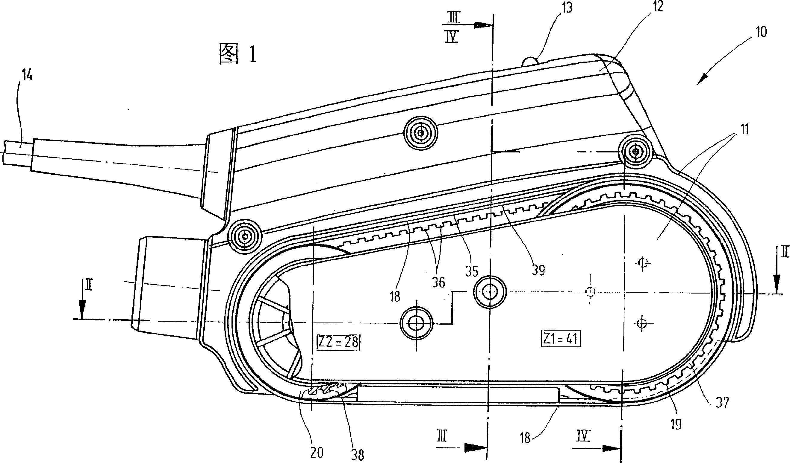
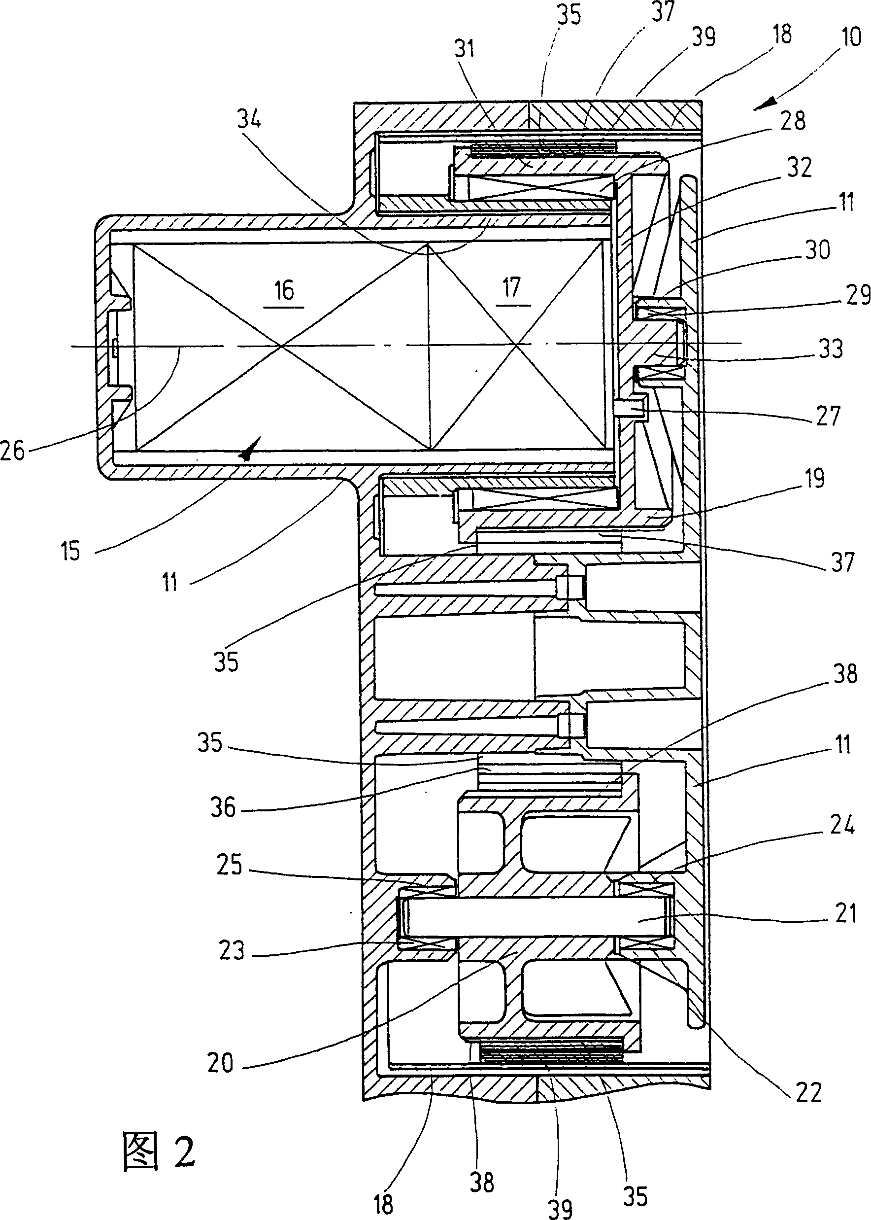
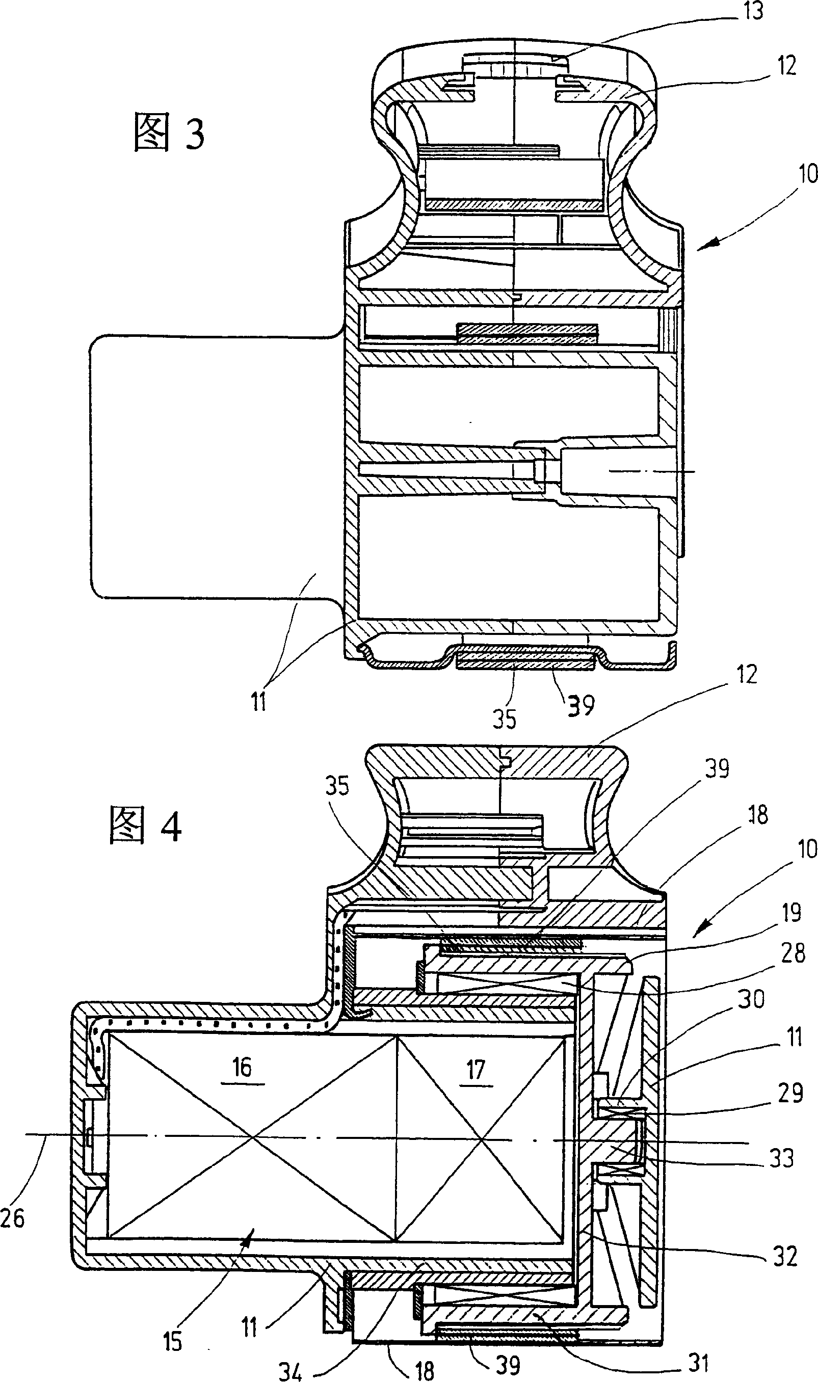
[0016] In the drawings, as an example of a portable abrasive belt grinder, a portable abrasive belt machine 10 is shown, which has a housing 11 on the upper side with a handle 12 that is, for example, substantially slat-shaped. The handle 12 contains a switch formed as a sliding switch 13 on the upper side in the right area in FIG. 1, through which the electric energy input via the wire 14 can be controlled, and the electric energy is used to drive the housing 11 uniformly marked with 15 Device power supply. The drive device 15 has an electric motor 16 with a transmission device 17 and is used to drive an abrasive belt 18, which is only shown schematically. The abrasive belt 18 can be separated from it by a rotatably driven drive roller 19 The steering roller 20 disposed at a distance in the housing 11 is rotatably guided, and can be driven by the rotational drive of the driving roller 19. The housing 11 is a multi-piece structure extending substantially in the longitudinal direct...


PUM


Abstract

The invention relates to a hand operated belt sander (10), comprising a housing (11), which accommodates a motor (16) with a gearbox (17) containing drive (15), for the sanding belt (18). Said belt may be run around a drive roller (19) which may be rotatably driven and, preferably, also a return roller (20). Said sander is smaller, more manageable and cheaper whereby the drive roller (19) is arranged and mounted coaxial to the drive (15) and driven directly by the drive from the gearbox (17).

Description

Technical field [0001] The invention relates to a portable sanding belt machine. Background technique [0002] This type of portable belt grinder is known in the form of a portable belt grinder. They are constituted as hand tools with a large size and a large weight, so they usually have two handles separated by a distance, and It is required to hold on both handles when in use. In order to achieve the desired ideal belt speed of the abrasive belt, a high-speed universal motor is used, and then the speed is reduced by combining a multi-stage transmission device in the form of a spur gear or bevel gear transmission with a toothed belt. Therefore, the output of the motor is mostly guided to a large gear placed at a distance from it via a small gear, and the two gears are connected by a toothed belt drive. The big gear itself drives a spur gear transmission, and a drive roller is arranged on the output shaft of the spur gear transmission. Therefore, the drive roller is spaced apart ...

Claims


Application Information

Patent Timeline
Patent Type & Authority Patents(China)
IPC IPC(8): B24B21/20B24B23/06
CPCB24B21/20B24B23/06
Inventor 斯特芬·温施
Owner ROBERT BOSCH GMBH
Why Eureka
Try Eureka