Foldable portable communication terminal device

A mobile communication terminal and display technology, which is applied in the direction of telephone communication, telephone structure, electrical components, etc., can solve the problems of heavy upper part and lack of weight balance, and achieve the effects of improved maneuverability, space saving, and slim appearance

Inactive Publication Date: 2004-08-11
PANASONIC CORP
View PDF0 Cites 0 Cited by
  • Summary
  • Abstract
  • Description
  • Claims
  • Application Information

AI Technical Summary

Problems solved by technology

[0009] In the second embodiment of the prior art, since, it only has a click structure, and the upper and lower shells cannot be folded one on top of the other, in terms of weight balance, there is a problem that the upper part is heavy, thus lacking in weight balance

Method used


Image

  • Foldable portable communication terminal device
  • Foldable portable communication terminal device
  • Foldable portable communication terminal device

Examples


no. 1 example

[0037] Now, refer to Figure 1 to Figure 5 , the first embodiment of the present invention will be described.

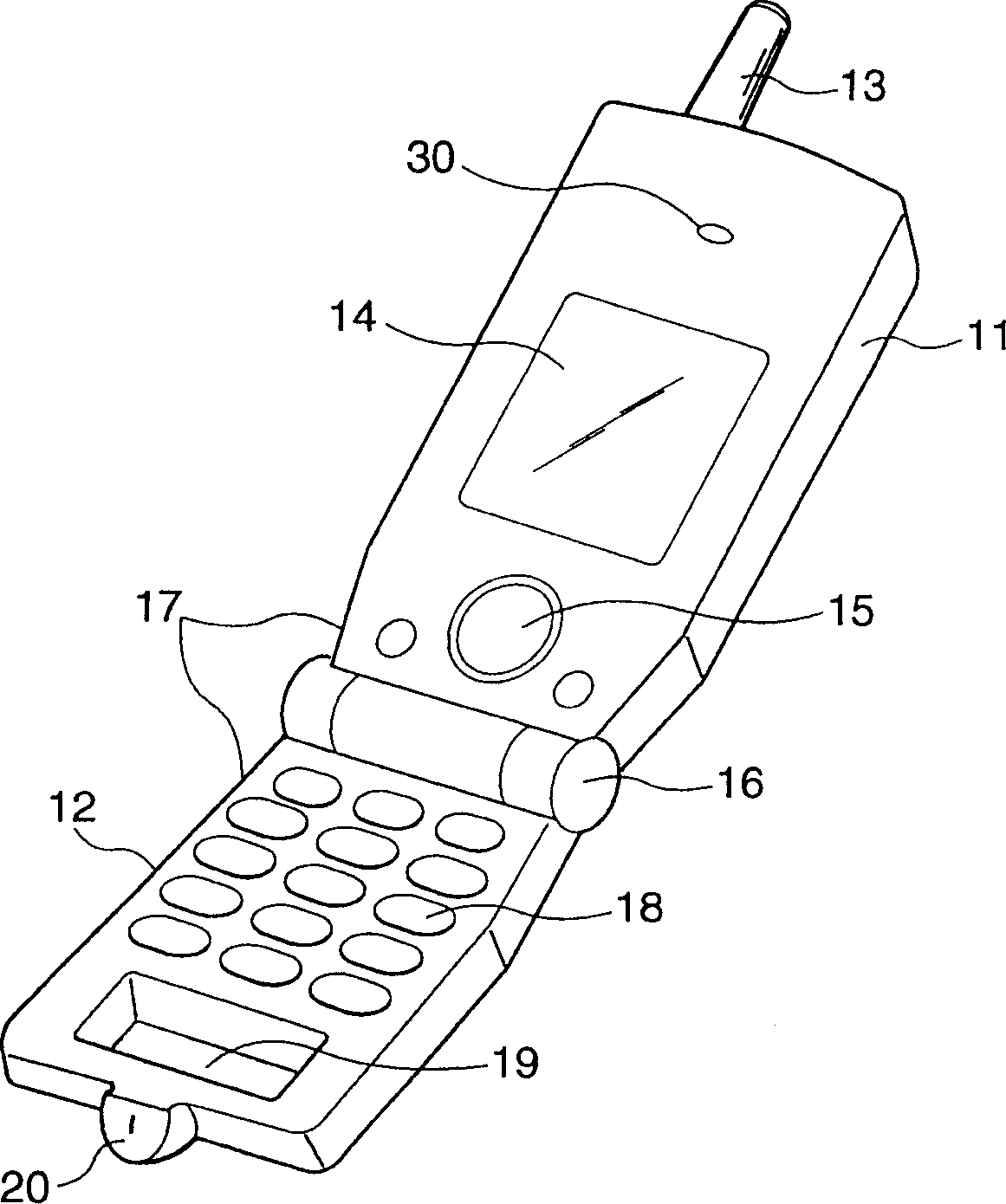
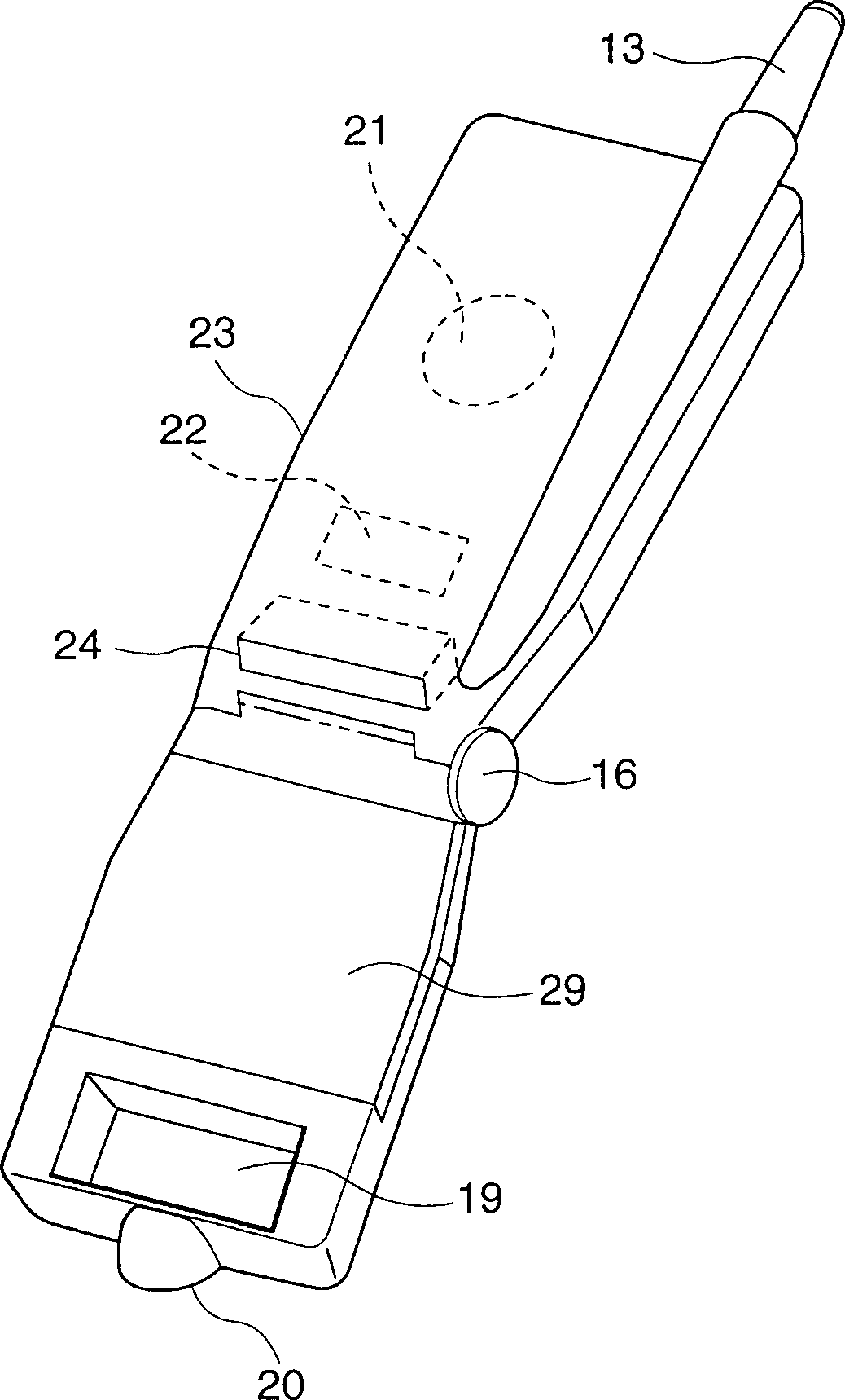
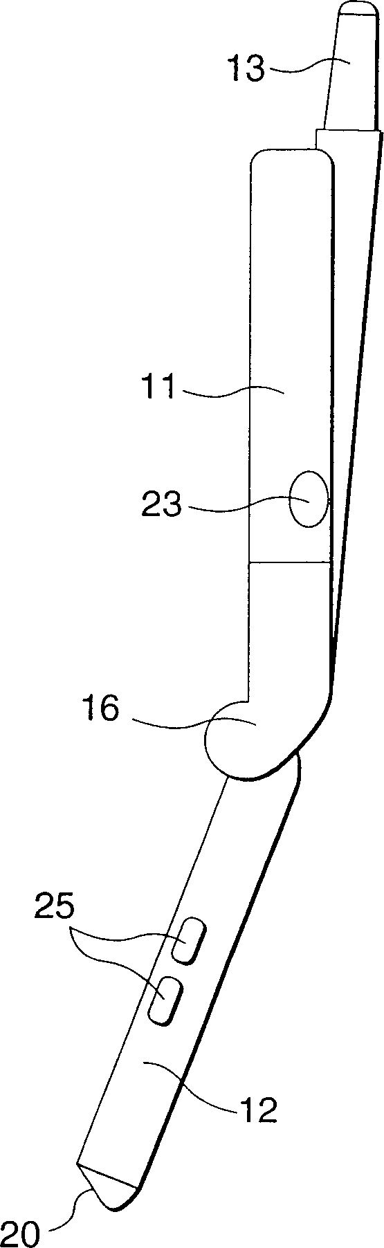
[0038] figure 1 is a perspective view of the foldable mobile communication terminal in an open position according to the first embodiment of the present invention; figure 2 is a rear perspective view of the foldable mobile communication terminal in an open position according to the first embodiment of the present invention; image 3 is a side view of the foldable mobile communication terminal in an open position according to the first embodiment of the present invention; Figure 4 is a side sectional view of the foldable mobile communication terminal in a closed position according to the first embodiment of the present invention; and Figure 5 It is a cross-sectional view showing the electrical connection between the upper case and the lower case and the general structure of the flexible board, and the functional blocks for each component are arranged on the fle...

no. 2 example

[0050] Refer to Figure 6 to Figure 9 , to illustrate the second embodiment of the present invention.

[0051] 6 is a perspective view of a foldable mobile communication terminal in an open state according to a second embodiment of the present invention; FIG. 7 is a rear perspective view of a foldable mobile communication terminal in an open state according to a second embodiment of the present invention; Figure 8 is a side sectional view of a foldable mobile communication terminal in a closed state according to a second embodiment of the present invention; Figure 9 It is a plan view showing the electrical connection between the upper case and the lower case, and the general structure of the flexible board, and the functional blocks for each element are arranged on the flexible board in the lower case;

[0052] The foldable mobile communication terminal of the present invention can be folded through the hinge portion 116 between the upper shell 111 and the lower shell 112, ...


PUM


Abstract

An upper case (11) houses a control unit (microcomputer) (not shown) having its function blocks mounted on a rigid substrate (27), a display unit (liquid crystal display) (14) and an RF communication unit (not shown), while a lower case (12) houses an operation unit (18) having its function blocks, even if they are many, mounted on a key substrate (flexible substrate (28)) and a battery (29). The result is that an antenna (13) is disposed in an RF communication unit-carrying upper case, with the key operation unit (18) and the battery (29) disposed in the lower case, whereby, unlike a conventional device, function blocks are disposed in the upper and lower cases with associated functions closed to each other to provide a lighter, smaller, and thinner device.

Description

technical field [0001] The present invention relates to a mobile communication terminal constructed in such a manner that an upper case and a lower case can be folded one on top of the other by a hinge, and in particular, to a mobile communication terminal in which the upper The number of wires between the case and the lower case is reduced, and elements are arranged to reduce the thickness of the upper case and the lower case. Background technique [0002] Generally, a mobile communication terminal that can be folded by a hinge as shown in FIGS. 10 and 11 is known. [0003] Fig. 10 shows a first embodiment of the prior art, wherein, Figure 10A is a plan view showing that the case part is separated in an open state, the upper part of the figure shows the upper case side, and the lower part shows the lower case side, and Figure 10B is a side view with the case part separated. [0004] The upper case side in FIG. 10 is configured such that an antenna 41 and a liquid crysta...

Claims


Application Information

Patent Timeline
Patent Type & Authority Patents(China)
IPC IPC(8): H04B1/38H04M1/02
CPCH04B1/3833H04M1/0214H04M1/0235
Inventor 林贵博久保哲也
Owner PANASONIC CORP
Why Eureka
Try Eureka