
High voltage transformer

A high-voltage, transformer technology, applied in transformers, inductors, televisions, etc., can solve problems such as large capacitance

Inactive Publication Date: 2004-08-11
KONINKLIJKE PHILIPS ELECTRONICS NV
View PDF1 Cites 0 Cited by
  • Summary
  • Abstract
  • Description
  • Claims
  • Application Information

AI Technical Summary

Problems solved by technology

The drawback of this damping circuit in the prior art is that the capacitance of the damping circuit is so large that it has to withstand high voltages

Method used


Image

  • High voltage transformer
  • High voltage transformer
  • High voltage transformer

Examples


Embodiment Construction

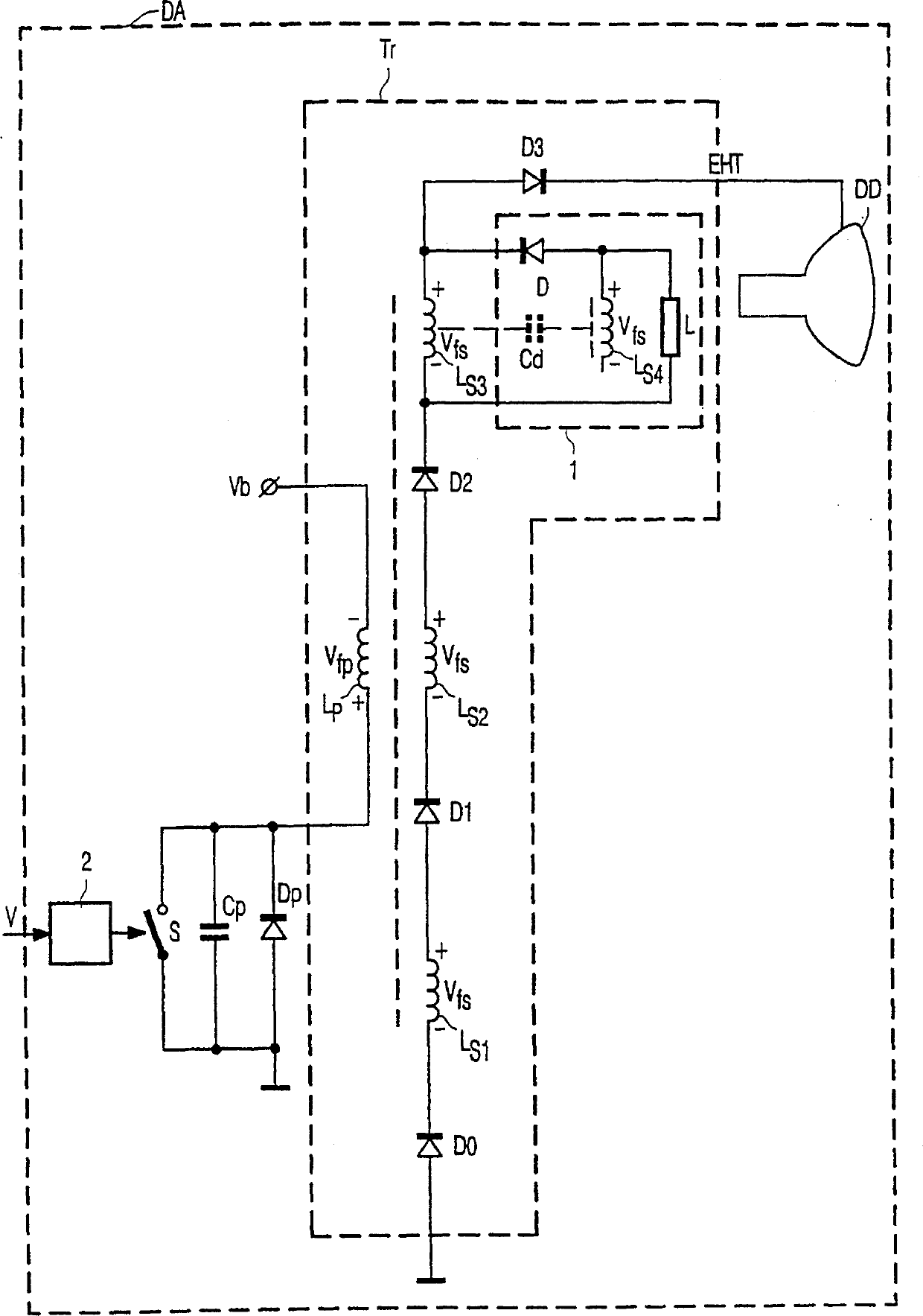
[0013] figure 1 A block diagram of a display device DA comprising a high-voltage transformer Tr with a damping circuit 1 according to a first embodiment of the invention is shown.

[0014] The display device DA includes a control circuit 2, a high voltage transformer Tr, a capacitor Cp, a diode Dp, and a display device DD. This display device can display video signals generated by a television or computer. The primary coil Lp and the switching element S of the high voltage transformer Tr arranged in series receive the power supply voltage Vb. Between ground and the connection point of the primary winding Lp and the switching element S, a capacitor Cp and a diode Dp are connected in parallel. The anode of the diode Dp is connected to the ground. The turn-on and turn-off periods of the switch element S are controlled by the control circuit 2 according to the horizontal synchronization signal separated from the input video signal V. It is also possible to use this line sync s...


PUM


Abstract

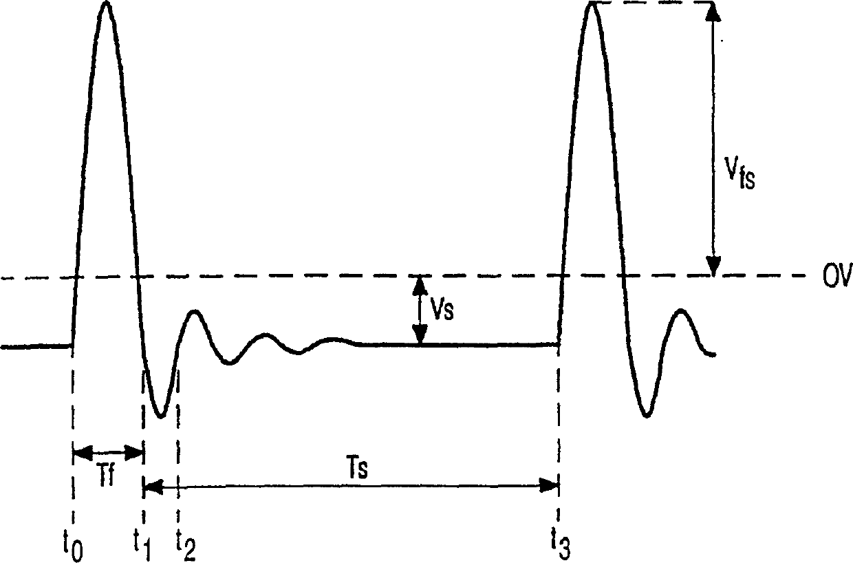
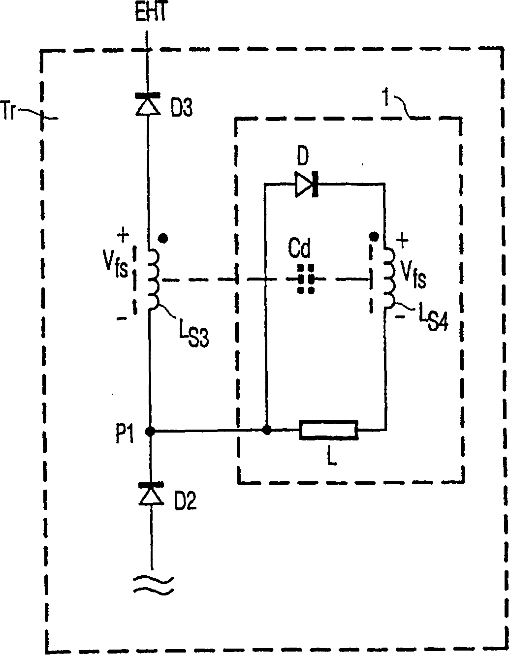
A high voltage transformer (Tr) includes a primary winding (Lp), secondary windings (Ls1, Ls2, Ls3), and diodes (Di) coupled between successive secondary windings. The polarity of the diodes and the secondary windings is selected such that the flyback voltages across each of the secondary windings are summed via conductive diodes during at least a part of a flyback period (Tf) for generating a high voltage. A damp-circuit (1) comprises a rectifier element, a load (L), and a further winding (Ls4) of the high voltage transformer. These elements are arranged with respect to one of the secondary windings such that the further winding and the one of the secondary windings form a capacitance (Cd) across the load. The diode (D) is non-conductive during the flyback period. In this way, electrical oscillations of the high voltage transformer are damped.

Description

technical field [0001] The present invention relates to a high voltage transformer comprising a high voltage coil for generating a high voltage during a flyback period (Tf), a rectifying element and a damping circuit of a load, wherein the rectifying element is arranged Make it non-conductive during the retrace period. The invention also relates to a display device with a display device for receiving a high voltage from a high voltage transformer comprising: a high voltage coil arranged to generate a high voltage during a retrace period, Also included is a rectifying element and a load damping circuit, wherein the rectifying element is arranged so that it does not conduct during the retrace period. Such a high voltage transformer is particularly suitable for generating an anode voltage for a cathode ray tube. Background technique [0002] Prior art DE-A-3830823 discloses a diode multi-head transformer for generating such high anode voltages. The diode multiple transformer...

Claims


Application Information

Patent Timeline
Patent Type & Authority Patents(China)
IPC IPC(8): H01F38/42H04N3/18H04N3/19
CPCH04N3/18H04N3/19
Inventor P·J·巴克斯R·永克曼
Owner KONINKLIJKE PHILIPS ELECTRONICS NV
Learn More