Three-D object recognition method and parts picking system using the method
A recognition method and technology of three-dimensional objects, applied in the field of parts grabbing system, can solve the problems of low recognition efficiency and long processing time.
- Summary
- Abstract
- Description
- Claims
- Application Information
AI Technical Summary
Problems solved by technology
Method used
Image

Examples
no. 1 example
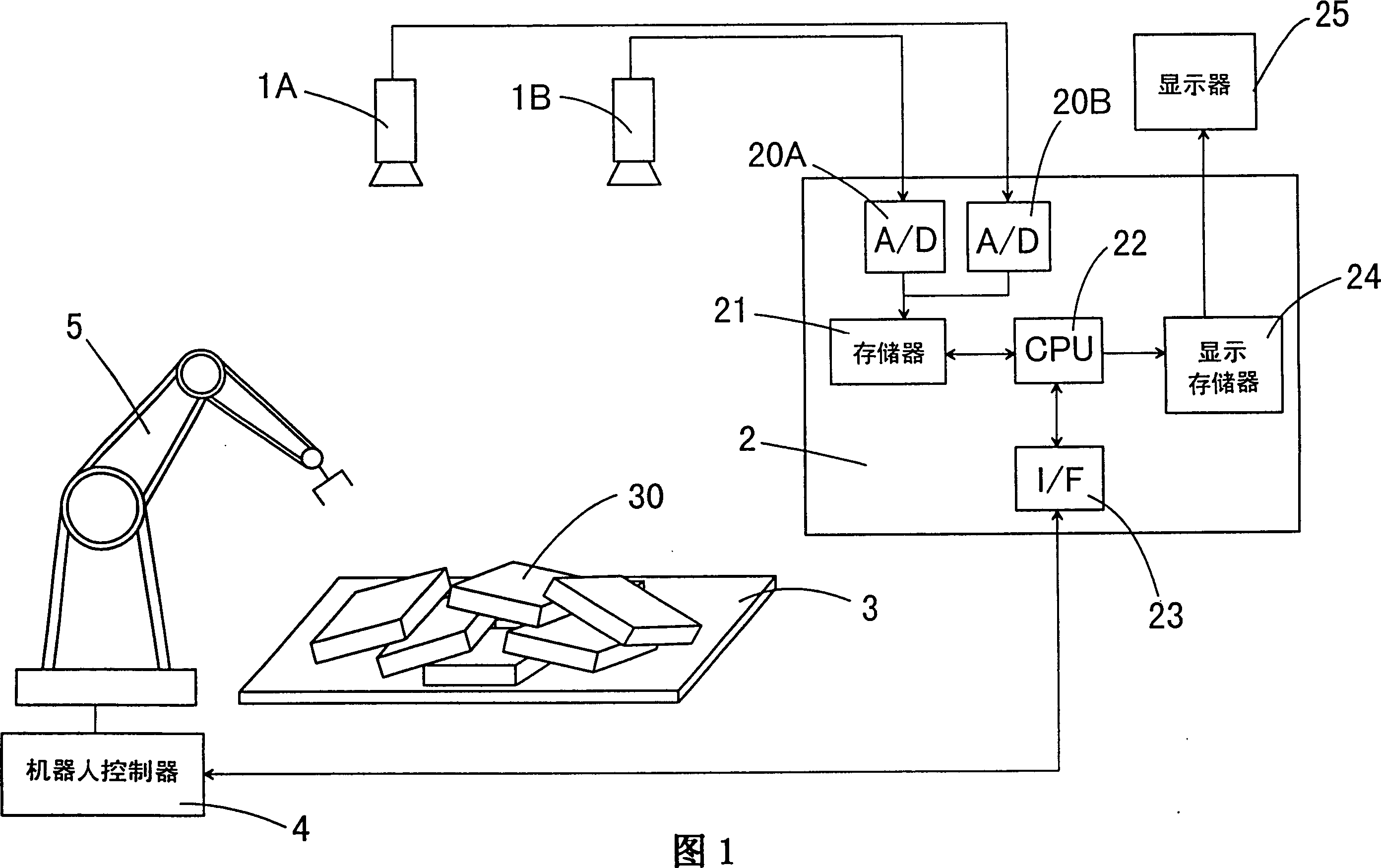
[0045]The three-dimensional object recognition method of the present invention can be well used in a part gripping system for conveying parts. For example, as shown in Figure 1, this part grasping system comprises a pair of TV cameras (1A, 1B); By using the image information provided by these TV cameras to carry out the image processing unit 2 of the three-dimensional object recognition method of the present invention; Have flexible robot 5 that can grasp parts 30 manipulator; And a robot controller 4, this robot controller 4 is used to control robot 5 according to the output that image processing unit 2 provides, makes manipulator grab parts from material box 30, wherein a plurality of parts 30 are piled up on the stage 3 in a random manner, and the grabbed parts are moved to the required positions.
[0046] In the image processing unit 2, the obtained video signal is converted into a digital signal by the A / D converter (20A, 20B), and temporarily stored in the memory 21. Ne...
no. 2 example
[0116] As shown in FIG. 14, the parts gripping system of the second embodiment is basically equal to the parts gripping system of the first embodiment, except that a third camera 1C is used in addition to the television camera, and by using the third camera 1C The image processing unit with A / D converter 20C can perform Figure 15 The 3D object recognition method shown.
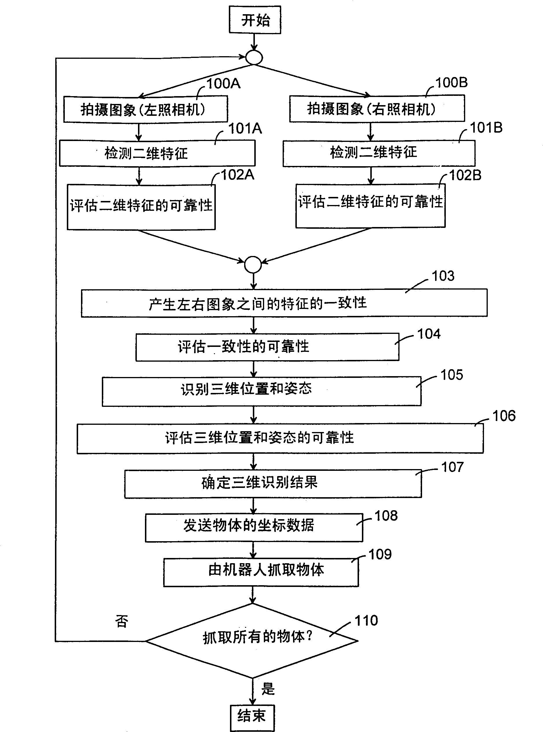
[0117] The three-dimensional object recognition method of the present embodiment includes the following steps: step 200A, photographing the left image; step 201A, detecting the two-dimensional features of the object on the left image; step 202A, evaluating the reliability of the two-dimensional features; step 200B, photographing The right image; step 201B, detecting the two-dimensional features of the object on the right image; step 202B, evaluating the reliability of the two-dimensional features. These steps are performed in the same manner as in the first embodiment. The method of this embodiment further ...
no. 3 example
[0126] The second embodiment described above illustrates that the recognition accuracy of the position and attitude of an object in three dimensions can be improved by creating consistency of two-dimensional features between the left and right images and between the left image and the third image. In this embodiment, the three-dimensional object recognition method is performed in consideration of the coincidence of the two-dimensional features between the generated right image and the third image.
[0127] Specifically, as Figure 16 As shown, a case where a rectangular solid 50 is used as an object is illustrated, and two parallel straight line pairs (51, 52), (53, 54) are used as two-dimensional features of the object. First, an image of a rectangular solid is taken using three cameras 1A, 1B and 1C. Next, two parallel line pairs (51, 52), (53, 54) are extracted from each of the three images as two-dimensional features. The first process of generating consistency between t...
PUM
 Abstract
Description
Claims
Application Information
 - R&D Engineer
- R&D Manager
- IP Professional
- Industry Leading Data Capabilities
- Powerful AI technology
- Patent DNA Extraction
Browse by: Latest US Patents, China's latest patents, Technical Efficacy Thesaurus, Application Domain, Technology Topic.
© 2024 PatSnap. All rights reserved.Legal|Privacy policy|Modern Slavery Act Transparency Statement|Sitemap