Image coding method and image coding device

An image coding and coding technology, applied in the direction of image coding, image communication, image data processing, etc., can solve the problem of not knowing the frame display period, difficult decoding processing circuit structure, not knowing the interval of I-VOP display timing and display timing, etc. question

Inactive Publication Date: 2004-08-18
PANASONIC INTELLECTUAL PROPERTY CORP OF AMERICA
View PDF1 Cites 0 Cited by
  • Summary
  • Abstract
  • Description
  • Claims
  • Application Information

AI Technical Summary

Problems solved by technology

[0044] As mentioned above, in the data structure of the image signal proposed in the current MPEG4, even if the frame rate is fixed, the value (size) of the frame rate is a structure in which the size of the frame rate is not known without decoding multiple frames, so it is difficult to simplify Problems with the Circuit Structure for Realizing the Practical Decoding Process
[0045] Simply put, as in Figure 17 As shown in (b), when VOP0 is an I-VOP (I frame), VOP1 and 2 are B-VOPs (B frames), and VOP3 is a P-VOP (P frame), in the bit stream as the image coded signal 200a ,like Figure 17 As shown in (c), since the frame F(0) corresponding to the I-VOP (I frame) is arranged next to the frame F(1) corresponding to the P-VOP (P frame) and the frame F(1) corresponding to the B-VOP (B frame) The corresponding frame F(2), so there is a problem that the frame display period (1 fixed VOP increment) is not known until the frame F(2) corresponding to the B-VOP (B frame) is transmitted, which is the case There is a problem of not knowing the interval between the display timing of the I-VOP and the display timing of the next B-VOP (B frame)

Method used


Image

  • Image coding method and image coding device
  • Image coding method and image coding device
  • Image coding method and image coding device

Examples


Embodiment 1

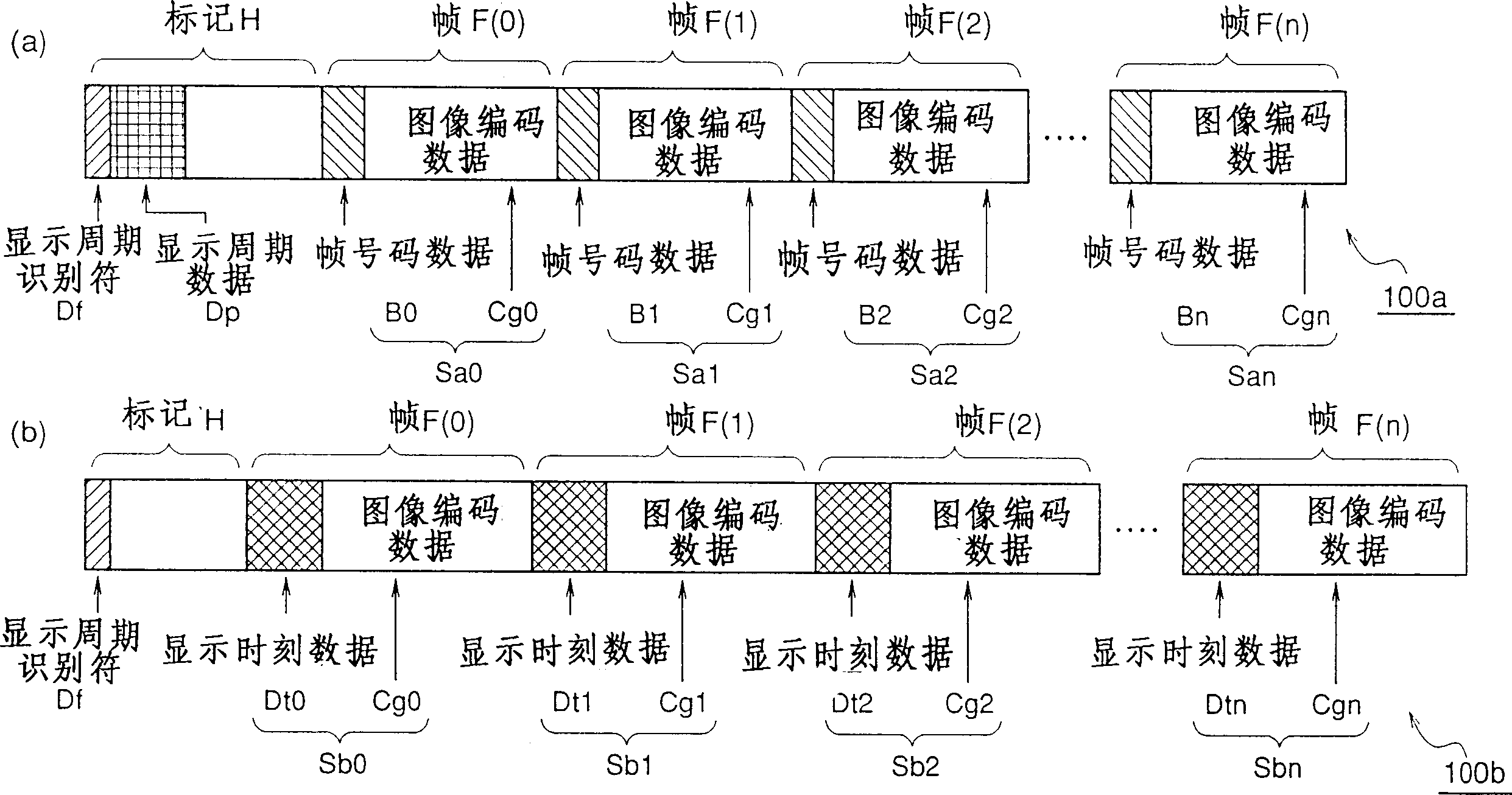
[0111] figure 1 (a) shows the data structure of the coded image signal 100a whose frame display period is fixed (constant) according to Embodiment 1 of the present invention, figure 1 (b) shows the data structure of the coded image signal 100b in which the frame display period is variable according to Embodiment 1 of the present invention.

[0112] The above-mentioned coded image signal 100a (refer to figure 1 (a)) is a signal corresponding to one image (an image corresponding to one object in MPEG4) and obtained by decoding an image signal whose frame display period is fixed. In H, symbol sequences Sa0, Sa1, Sa2, ..., San corresponding to frames F(0), F(1), F(2), ..., F(n) are arranged in the order of transmission. Here, n is a number corresponding to data transfer of each frame in a series of frames constituting one image.

[0113] In this coded image signal 100a, a display period identifier (display period fixed identifier) ​​Df indicating that the frame display perio...

Embodiment 2

[0204] Figure 7 (a) shows the data structure of the image coded signal 120a whose frame display period is constant in Embodiment 2 of the present invention.

[0205] The image coded signal 120a is a signal corresponding to one image (an image corresponding to one object in MPEG4) and a coded frame display cycle is fixed. The corresponding symbol sequences Sc0, Sc1, Sc2, ..., Scn of each frame F(0), F(1), F(2), ..., F(n). In this coded image signal 120a, a display period identifier Df indicating whether the frame display period is fixed is inserted in the header H, and a multiplier M (natural number) is used to indicate that the frame display period is M times the minute unit time (1 / N). Display period multiplier data Dm and micro-unit time data Dk representing the value N (natural number) for calculating the above-mentioned micro-unit time (1 / N); at the head of the symbol sequence Sc0, Sc1, Sc2, ..., Scn of each frame Insertion represents the display time y'0, y'3, y'1, ......


PUM


Abstract

The present invention relates to a data structure of an image signal, image encoding and decoding method. The data structure of the invention is capable of reducing the bit number required by the defined display time when the frame has a fixed display cycle, comparing with the foregone image data structure. Furthermore, this data structure can be applied to a coded image signal having a variable display cycle. A data structure of an image signal includes a reproduction cycle identifier indicating whether the cycle of image display for each frame is variable or not. When the display cycle identifier indicates that the display cycle is fixed, display cycle data is inserted in a labeled part of the image data, and data relating to the frame number is inserted in each frame. On the other hand, when the display cycle identifier indicates that the display cycle is variable, display time data is inserted for each frame.

Description

[0001] This application is a divisional application with the application number 98121454.1, the application date is October 30, 1998, and the invention title is "image signal data structure, image encoding method and decoding method". technical field [0002] The present invention relates to an image signal data structure, an image encoding method, and an image decoding method, and in particular, relates to reproduction timing data including reproduction timing data related to the timing of reproduction processing including encoding processing and image display processing corresponding to each frame of an image. image signal structure; generation (encoding processing) of an image coded signal including the reproduction timing data; and decoding process of the image coded signal. [0003] Furthermore, the present invention relates to an image encoding device for generating the above-mentioned image encoding signal and an image decoding device for performin...

Claims


Application Information

Patent Timeline
Patent Type & Authority Patents(China)
IPC IPC(8): H04N5/92G06T9/00H04N7/08H04N7/081H04N7/24H04N7/50H04N7/52H04N19/00H04N19/46H04N19/503H04N19/70H04N19/85H04N21/2343H04N21/235H04N21/236H04N21/242H04N21/43H04N21/434H04N21/435H04N21/6332H04N21/654
CPCH04N21/242H04N7/26313H04N7/52H04N21/4307H04N21/23614H04N21/4348H04N21/435H04N21/654H04N21/234318H04N7/50H04N21/235H04N21/6332H04N19/46H04N21/43072H04N21/236H04N19/115
Inventor 西孝启角野真也文仲丞
Owner PANASONIC INTELLECTUAL PROPERTY CORP OF AMERICA
Why Eureka
Try Eureka