Electric incandescent lamp

A technology for incandescent lamps and incandescent bodies, which is applied in the direction of incandescent lamps, incandescent lamp parts, discharge lamps, etc., and can solve problems such as lamp leakage, high early failure rate, and short life

Inactive Publication Date: 2004-11-10
KONINKLIJKE PHILIPS ELECTRONICS NV
View PDF2 Cites 0 Cited by
  • Summary
  • Abstract
  • Description
  • Claims
  • Application Information

AI Technical Summary

Problems solved by technology

The position of its incandescent body relative to the lamp cap is only determined within a wide r...

Method used


Image

  • Electric incandescent lamp
  • Electric incandescent lamp
  • Electric incandescent lamp

Examples


Embodiment Construction

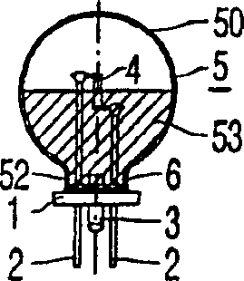
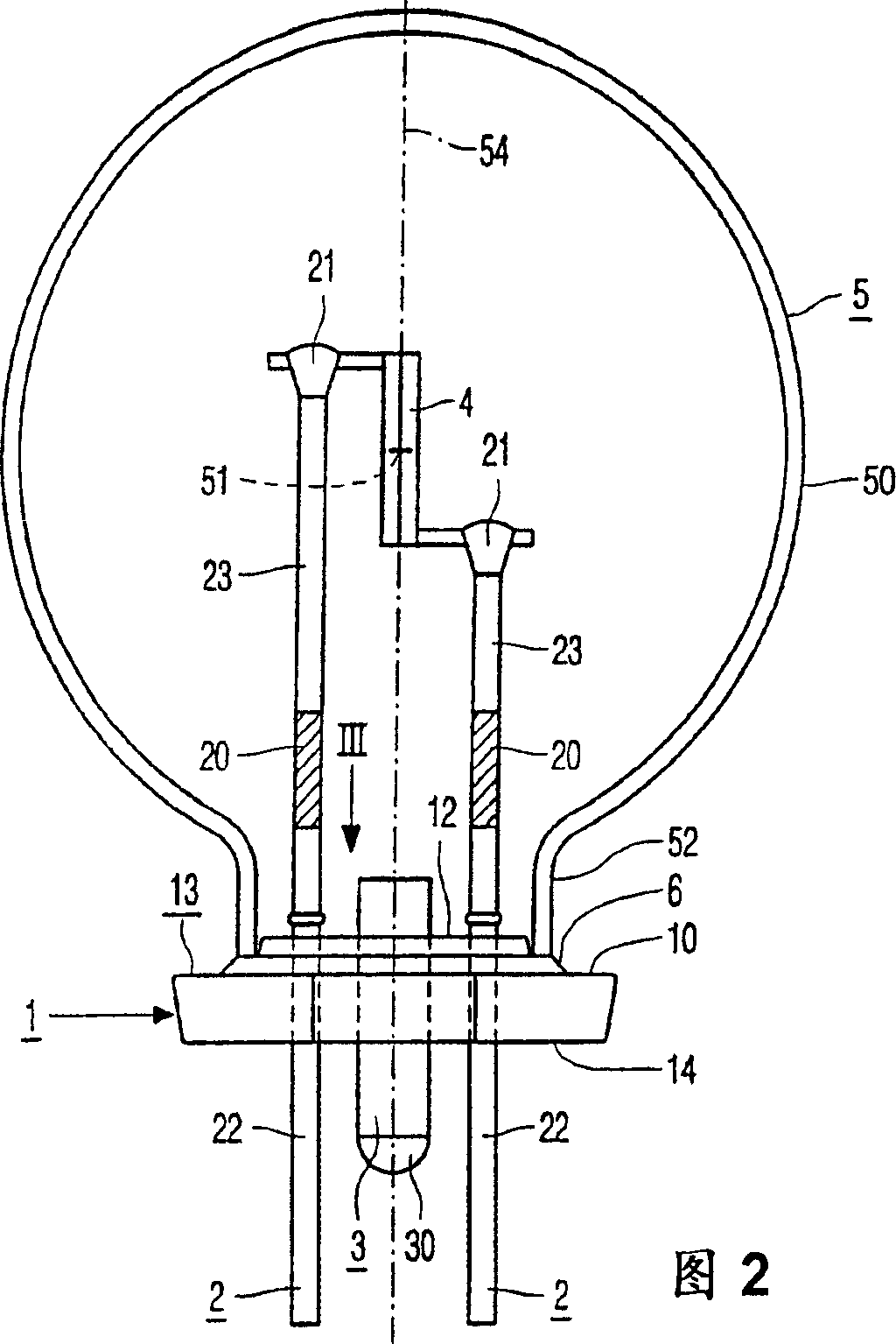
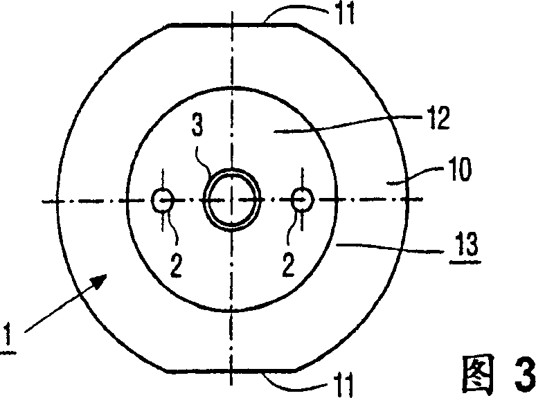
[0035] exist figure 1 and 2, the electric incandescent lamp has a sintered plate 1 of glass, which is connected in a gas-tight manner to a current conductor 2 and a metal tube 3 passing through the plate. The incandescent body 4 is connected to the current conductor 2 and is in a predetermined position relative to the sintered plate 1 . The glass bulb 5 is arranged above the incandescent body 4 and is connected to the sintered plate in an airtight manner via an enamel 6 . Filling gas at a pressure of at least 1 bar is present in the bulb 5 . The metal tube 3 has a gas-tight seal 30 outside the bulb 5 .

[0036] The sintered plate 1 is made of a first glass with a linear thermal expansion coefficient corresponding to the linear thermal expansion coefficient of the second glass of the bulb 5, the first and second glasses having 11*10 -6 K -1 coefficient of linear thermal expansion. In the accompanying drawings, the glass composition of the sintered plate 1 is basically: SiO...


PUM


Abstract

The electric incandescent lamp has a sintered glass plate (1) through which current conductors (2) and a metal tube (3) extend. An incandescent body (4) is connected to said current conductors (2) aligned with respect to the sintered plate (1). A glass bulb (5) is present over the incandescent body (4), gastight secured to the sintered plate (1) by means of enamel (6). A water getter (20) and a heavy gas at an elevated pressure are present inside the glass bulb (5). The lamp may consume a relatively high power and may be relatively small, but nevertheless has a relatively long life.

Description

technical field [0001] The invention relates to an incandescent electric lamp, comprising: [0002] a shaped glass sheet connected in a gas-tight manner to current conductors and metal tubes extending through the sheet; [0003] an incandescent body in a predetermined position relative to the shaped plate and connected to the current conductor; [0004] glass bulb, surrounding the incandescent body, connected in a gas-tight manner to the shaped plate by means of enamel; [0005] Filled with gas, having a pressure of at least 1 bar inside the bulb; [0006] The metal tube has a gas-tight seal outside the bulb. Background technique [0007] Such an electric incandescent lamp is known from FR-B-913579. [0008] Known lamps have a molded or pressed glass plate with a circular rim on which a positioning peg is located. The lamp is designed so as to pass through the opening in the reflector with its bulb at the front and to be pushed down so that the edge of the plate rests a...

Claims


Application Information

Patent Timeline
IPC IPC(8): H01K1/28H01J61/36H01K1/16H01K1/36H01K1/50H01K1/56
CPCH01J61/302H01K1/36H01J61/363H01J61/36
Inventor U·布鲁格曼W·L·科尔曼J·M·J·格贝尔斯A·J·M·范赫斯
Owner KONINKLIJKE PHILIPS ELECTRONICS NV
Why Eureka
Try Eureka