Antenna device radio device using the device, and radio repeater

An antenna device and antenna technology, which is applied in the direction of the radio relay system, the mid-position feed between the antenna endpoints, the antenna, etc., can solve the problems of the complex structure of the amplifier, the bulky size, and the reduction of the gain improvement effect

Inactive Publication Date: 2004-12-01
PANASONIC CORP
View PDF7 Cites 2 Cited by
  • Summary
  • Abstract
  • Description
  • Claims
  • Application Information

AI Technical Summary

Problems solved by technology

[0017] And, especially in the rhombic antennas with multiple slit ends as shown in Fig. 3 or the antennas arranged in parallel connection or serial connection, due to the mutual coupling between adjacent 1-wavelength units, the center The current distribution of nearby antenna elements cannot be optimized
As a result, there arises a problem that the effect of gain improvement caused by multiple antenna arrangements is reduced
[0018] On the other hand, in the above-mentioned conventional wireless repeater, the structure of the amplifier capable of obtaining a larger repeater gain becomes complicated and bulky
Therefore, there arises such a problem that a bulky amplifier cannot be properly placed in an indoor type small repeater device

Method used


Image

  • Antenna device radio device using the device, and radio repeater
  • Antenna device radio device using the device, and radio repeater
  • Antenna device radio device using the device, and radio repeater

Examples


no. 1 example

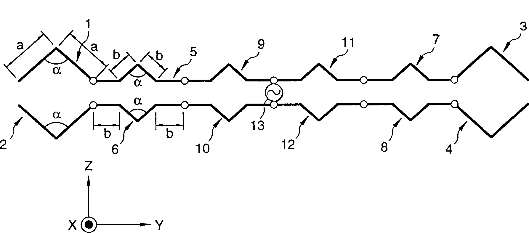
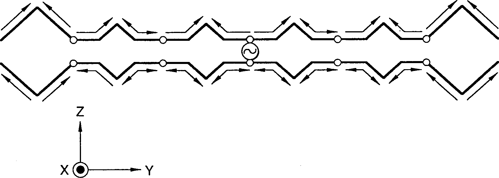
[0050] In the antenna device according to the first embodiment mode, a pair of slit-ended rhombic antennas are arranged at both end portions, and four 1-wavelength loop antennas are connected in such a manner that two 1-wavelength antennas each The half-wavelength antenna portion of the center portion is bent at three points in a symmetrical manner with respect to a straight line perpendicularly intersecting the 1-wavelength antenna element. Both ends of the 1-wavelength loop antenna are connected to a pair of rhombic antennas as described above, and a common power supply unit is provided.

[0051] Such as figure 1 As shown, the antenna device of the first embodiment mode is provided with antenna elements 1 to 12 and a power supply unit 13 .

[0052] The antenna elements 1 to 12 are arranged by wires having a length of one wavelength, and are bent at an angle "α" at the center portion thereof. Usually, the angle "α" is set to about 30 to 150 degrees. In this embodiment mod...

no. 2 example

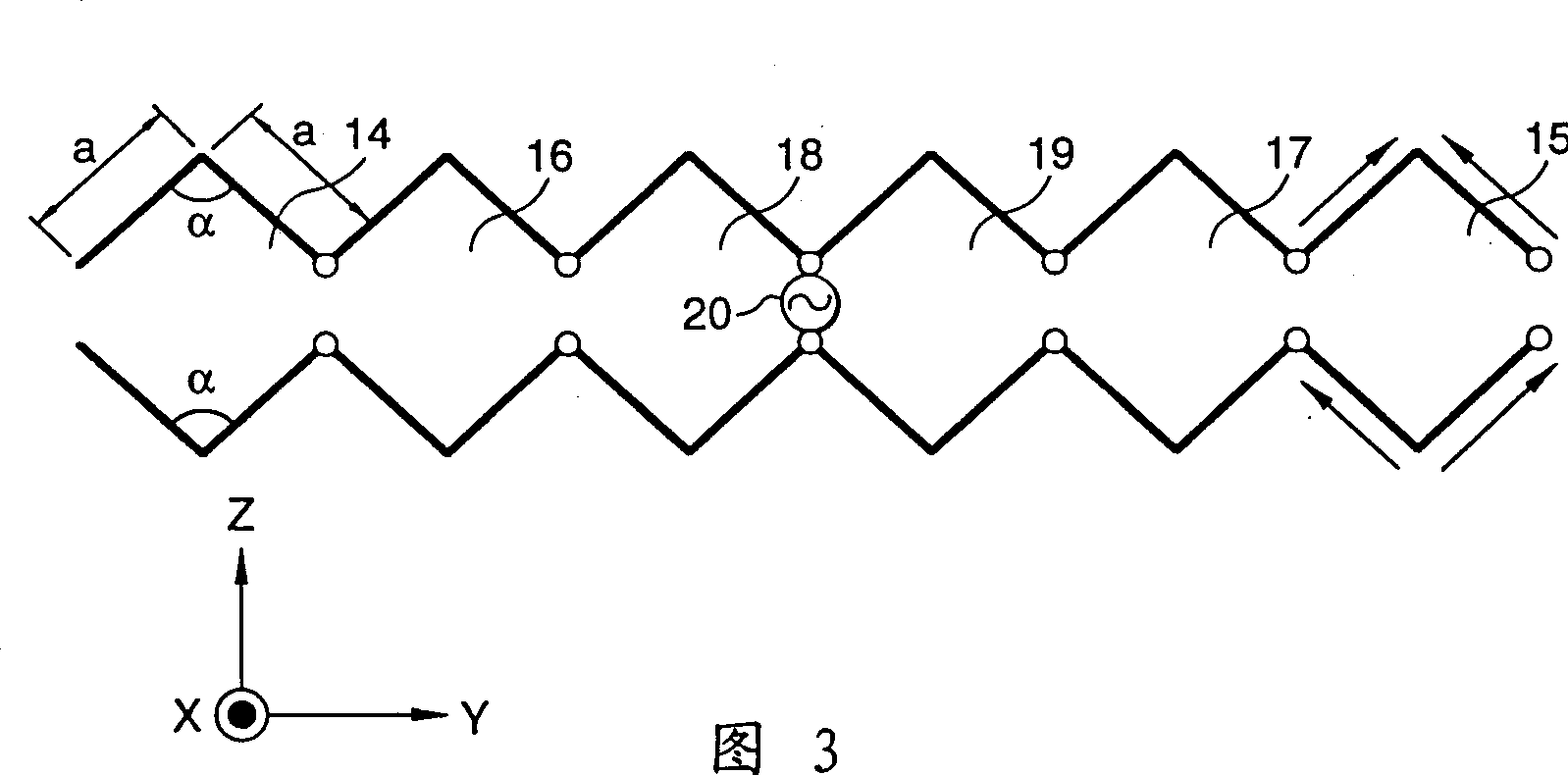
[0060] In the antenna device according to the second embodiment mode, a pair of slit-ended rhombic antennas are arranged at both end portions, and four 1-wavelength loop antennas are arranged in such a manner that two 1-wavelength antenna elements each A half-wavelength antenna portion of a central portion is bent in a semicircle. Both ends of the 1-wavelength loop antenna are connected to a pair of rhombic antennas as described above, and a common power supply unit is further provided.

[0061] Such as Figure 5 As shown, the antenna device of the second embodiment mode is provided with antenna elements 1 and 2, antenna elements 26 to 33. should be understood as figure 1 The same reference numbers shown will be used to represent Figure 5 The same, or similar, structures are shown and may operate in the same manner.

[0062] The antenna elements 26 to 33 are arranged by wires having a length of 1 wavelength, and are bent into a semicircle at their centers with a length "...

no. 3 example

[0066] In the antenna device according to the third embodiment mode, the antenna of the first embodiment mode is formed on a printed board, and further the reflection plate is fixed at a position spaced from the back of the printed board by a predetermined distance.

[0067] Such as Figure 6 As shown, the antenna device according to the third embodiment mode is provided with a dielectric board 34 , an antenna pattern 35 , a power supply unit 36 ​​, a post 37 , and a reflection board 38 .

[0068] The dielectric board 34 is a printed board made of, for example, a glass epoxy board, and the antenna pattern 35 is made of a printed pattern formed on the dielectric board 34 . Antenna pattern 35 is constructed to have a figure 1 The antenna elements 1 to 12 provided in the shown antenna arrangement are of the same shape. The power supply unit 36 ​​is arranged at the central portion of the antenna pattern 35 .

[0069] The dielectric plate 34 is fixed on the reflection plate 38 ...


PUM


Abstract

Antenna elements (1 to 4) are arranged to form rhombuses, each side having a length (a) of a half wavelength ( lambda / 2). Antenna elements (5 to 12) are bent at three points so that each side can have a length (b) of a quarter wavelength ( lambda / 4). Groups of antenna elements (1 to 4), (5 to 8) and (9 to 12) are connected as shown in the figure. The antenna elements (9, 10) and the antenna elements (11, 12) are connected to a feeder (13). This configuration provides a high-gain antenna having a simplified flat structure.

Description

technical field [0001] The invention relates to an antenna device, a wireless device and a wireless relay device using the antenna device. The antenna device is used in mobile communication systems mainly known as PHS (Personal Handyphone System) systems. technical background [0002] Generally, in an outdoor small base station device (main unit) implemented in a mobile communication system such as a PHS system, although an omnidirectional antenna such as a bushing antenna is used, the antenna gain of the omnidirectional antenna is less than or approximately equal to 2dBi. Also, a local wireless network (Wireless Local Loop: WLL) uses a mobile communication system such as a PHS system, and in a fixed terminal device used therein, an antenna gain of about 10 dBi is required. [0003] Recently, in mobile communication systems as described above, antennas are required to have high gain in order to expand the communication coverage area. These antennas are used in indoor small...

Claims


Application Information

Patent Timeline
Patent Type & Authority Patents(China)
IPC IPC(8): H01Q11/14H01Q9/26H01Q9/28H01Q11/06H04B1/38H04B1/3822H04B7/15
CPCH01Q11/06H01Q9/28H01Q9/26
Inventor 斋藤裕春木宏志
Owner PANASONIC CORP
Why Eureka
Try Eureka