Vehicular glass-mount antenna and system

a glass-mount antenna and glass-mount technology, applied in the field of vehicle glass-mount antennas, can solve the problems of high cost, high cost, and difficult electromagnetic coupling of such antennas in sdars applications, and achieve the effects of high cost, high cost, and high cos

Active Publication Date: 2005-09-08
DELPHI TECH INC
View PDF16 Cites 18 Cited by
  • Summary
  • Abstract
  • Description
  • Claims
  • Application Information

AI Technical Summary

Problems solved by technology

Thus, the mounting location for SDARS patch antennas makes antenna reception a sensitive issue with respect to the position of the antenna on a vehicle.
Electromagnetically coupling such antennas in an SDARS application, without an external amplifier, is very difficult due to inherent...

Method used


Image

  • Vehicular glass-mount antenna and system
  • Vehicular glass-mount antenna and system
  • Vehicular glass-mount antenna and system

Examples


Embodiment Construction

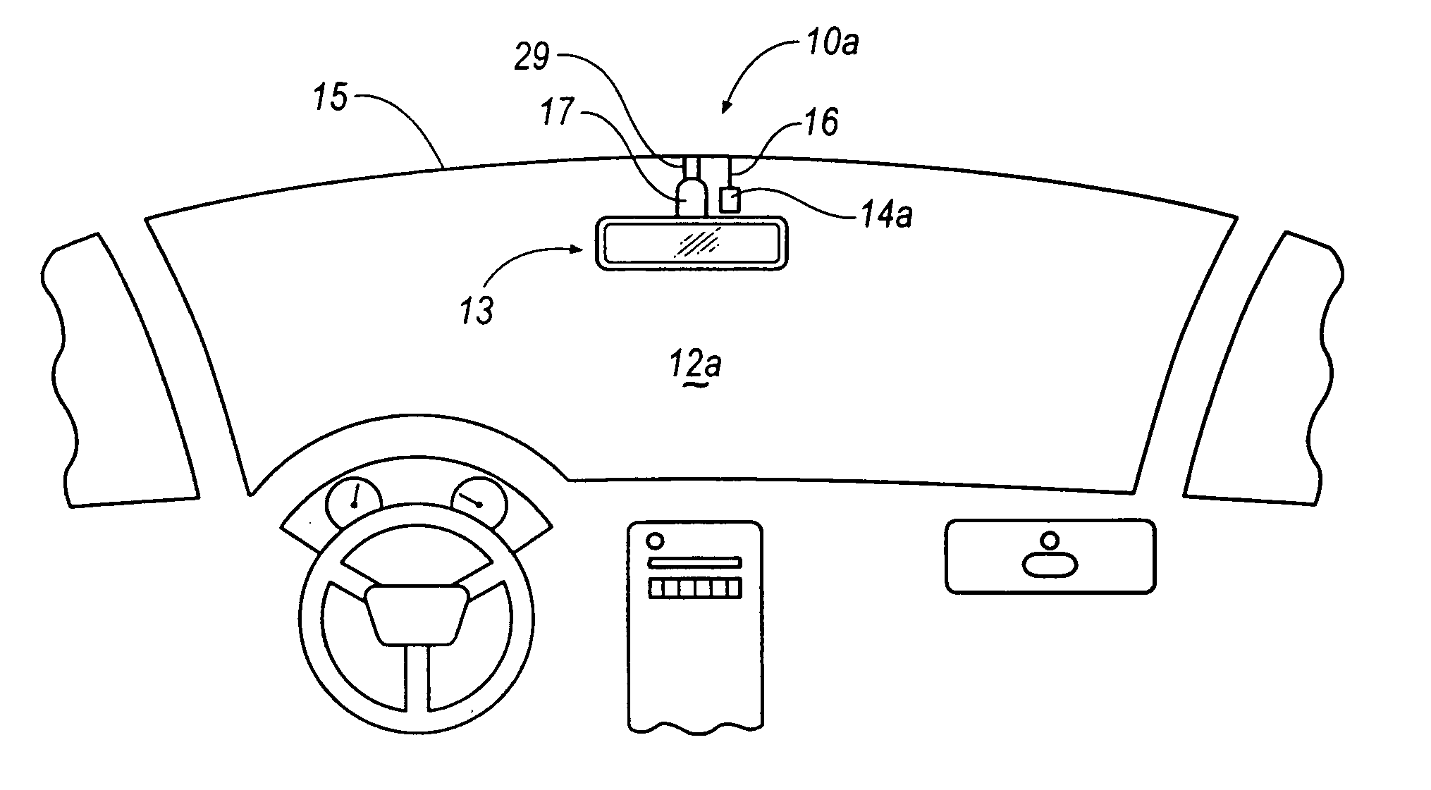
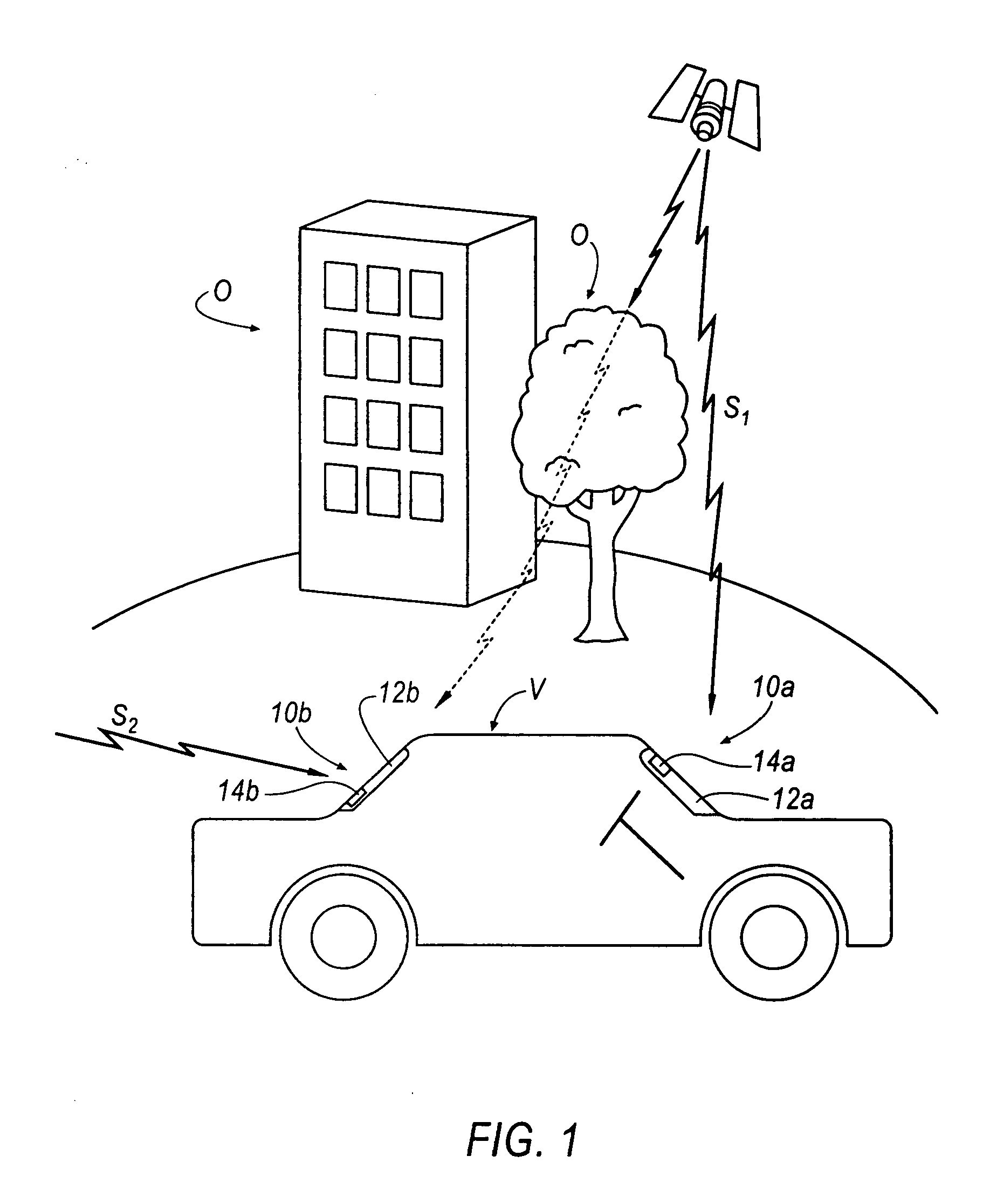
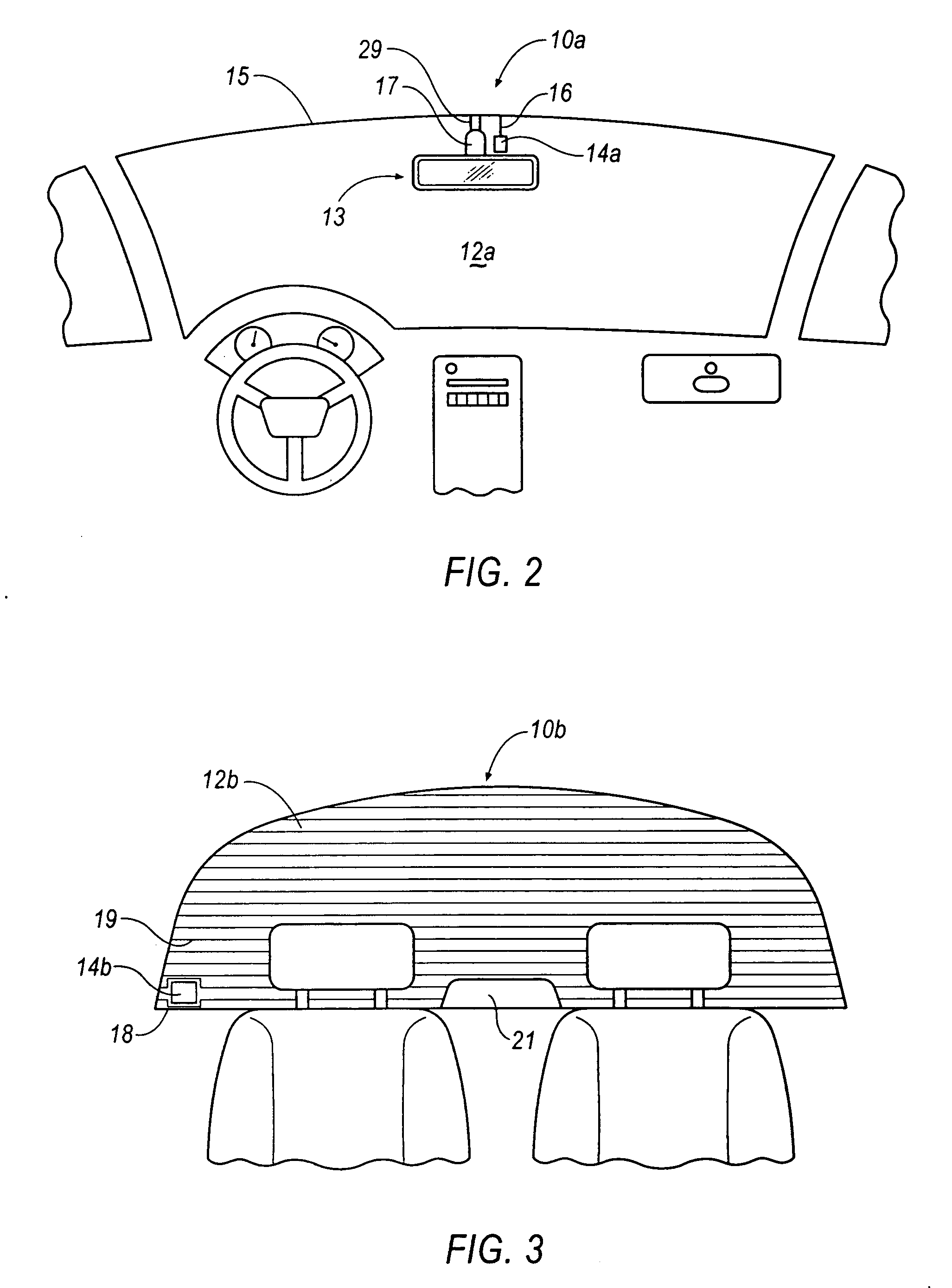
[0024] The above described disadvantages are overcome and a number of advantages are realized by inventive antenna systems, which are generally illustrated at 10a, 10b in FIGS. 1-3. As illustrated in FIG. 1, a vehicle, V, includes a front windshield glass 12a and rear windshield glass 12b each including antenna units 14a, 14b, respectively. Referring to FIG. 2, the antenna unit 14a is shown proximate a rear-view mirror assembly 13 at a top portion 15 of the front windshield glass 12a that meets a headliner (not shown). The location of headliner provides the shortest path to route and hide wires 16 extending from the antenna unit 14a and rear-view mirror assembly 13. When implemented near the top portion 15, the antenna unit 14a should not come into direct contact with the vehicle body so as to ensure that the antenna unit 14a is not shorted out. As seen in FIG. 3, the antenna unit 14b is located near a corner 18 of the rear windshield glass 12b such that defroster wires 19 are route...


PUM

PropertyMeasurementUnit
Angleaaaaaaaaaa
Angleaaaaaaaaaa
Angleaaaaaaaaaa

Abstract

An antenna system for a vehicle including a front windshield glass and a rear windshield is disclosed. The antenna system comprises an antenna unit including a radiating element electromagnetically coupled to an excitation element. The radiating element is coupled to the front windshield glass, and the excitation element is positioned on a passenger compartment interior surface of the front windshield glass. The antenna system also comprises a high-gain antenna unit including first radiating elements, a second radiating element, a 90-degree phase shift circuit, and a low noise amplifier that is coupled to the phase shift circuit. The first radiating elements receive signals through the rear windshield glass. The antenna unit and the high-gain antenna unit may function in a diversity antenna configuration.

Description

RELATED APPLICATIONS [0001] This application claims priority to U.S. provisional patent application Ser. No. 60 / 550,280 filed Mar. 5, 2004.TECHNICAL FIELD [0002] The present invention generally relates to vehicular glass-mount antennas having improved radiation characteristics. BACKGROUND OF THE INVENTION [0003] It is known in the art that automotive vehicles are commonly equipped with audio radios that receive and process signals relating to amplitude modulation / frequency modulation (AM / FM) antennas, satellite digital audio radio systems (SDARS) antennas, global positioning system (GPS) antennas, digital audio broadcast (DAB) antennas, dual-band personal communication systems digital / analog mobile phone service (PCS / AMPS) antennas, Remote Keyless Entry (RKE) antennas, Tire Pressure Monitoring System antennas, and other wireless systems. [0004] Currently, patch antennas are employed for reception and transmission of GPS [i.e. right-hand-circular-polarization (RHCP) waves] and SDARS ...

Claims


Application Information

Patent Timeline
IPC IPC(8): H01Q1/12H01Q1/32H01Q9/04H01Q21/24
CPCB32B17/10036B32B17/10174B60C23/0444H01Q1/1285H01Q21/24H01Q1/325H01Q9/04H01Q9/0414H01Q9/0428H01Q1/3233
Inventor YEGIN, KORKUTMORRIS, DANIEL G.SNOEYINK, RANDALL J.LIVENGOOD, WILLIAM R.
Owner DELPHI TECH INC
Why Eureka
Try Eureka