
Floor area required less vibrating screen

A vibrating screen and screen box technology, which is applied in the direction of filter screen, solid separation, grille, etc., can solve the problems that equipment transformation cannot be carried out, equipment investment is increased, and the space of vibrating screen is small, so as not to affect the screening efficiency and screening efficiency. Accuracy, reduce equipment installation land, reduce the effect of installation land

Inactive Publication Date: 2004-12-29
孙功民
View PDF0 Cites 0 Cited by
  • Summary
  • Abstract
  • Description
  • Claims
  • Application Information

AI Technical Summary

Problems solved by technology

[0002] Vibrating screens in the prior art are generally installed end-to-end in a row. Therefore, the amount of land required for equipment installation is extremely large, which increases equipment investment and costs.
Especially when renovating old equipment, there is very little space to install the vibrating screen. If the installation method of the vibrating screen is not improved, the equipment remodeling will not be possible.

Method used


Image

  • Floor area required less vibrating screen
  • Floor area required less vibrating screen

Examples


Embodiment Construction

[0007] In order to clearly illustrate the technical features of the solution, the solution will be described below through a specific implementation.

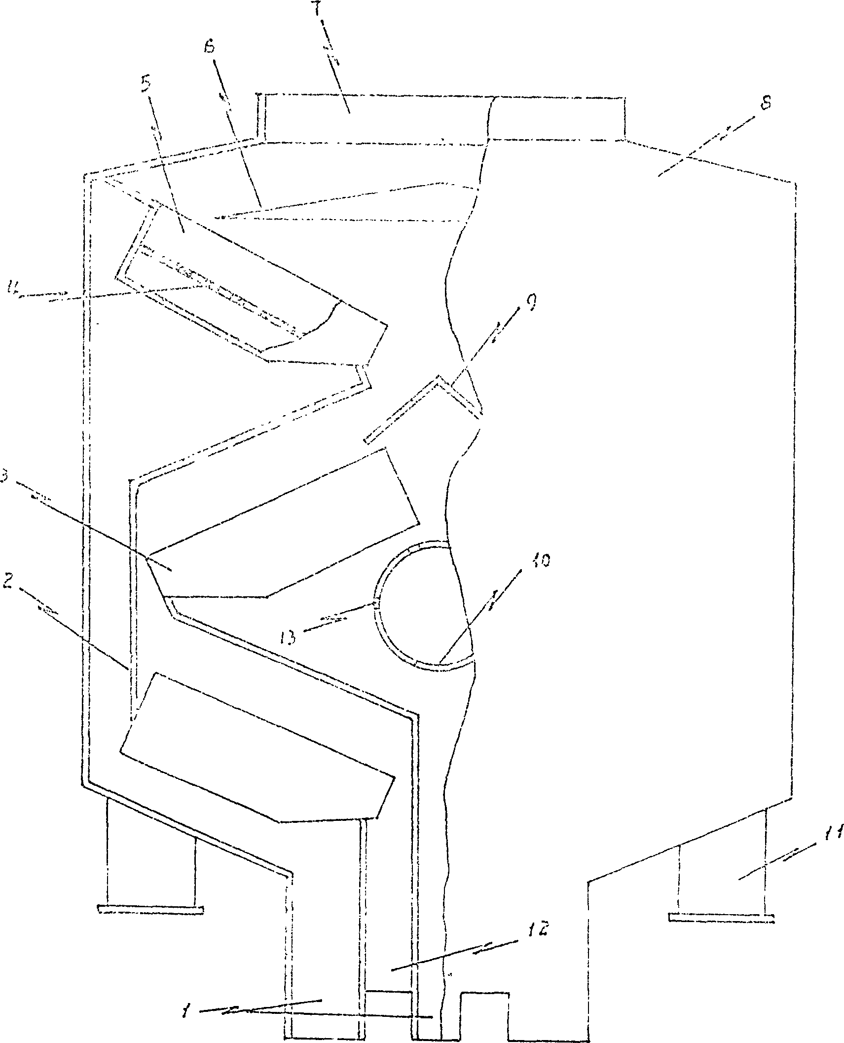
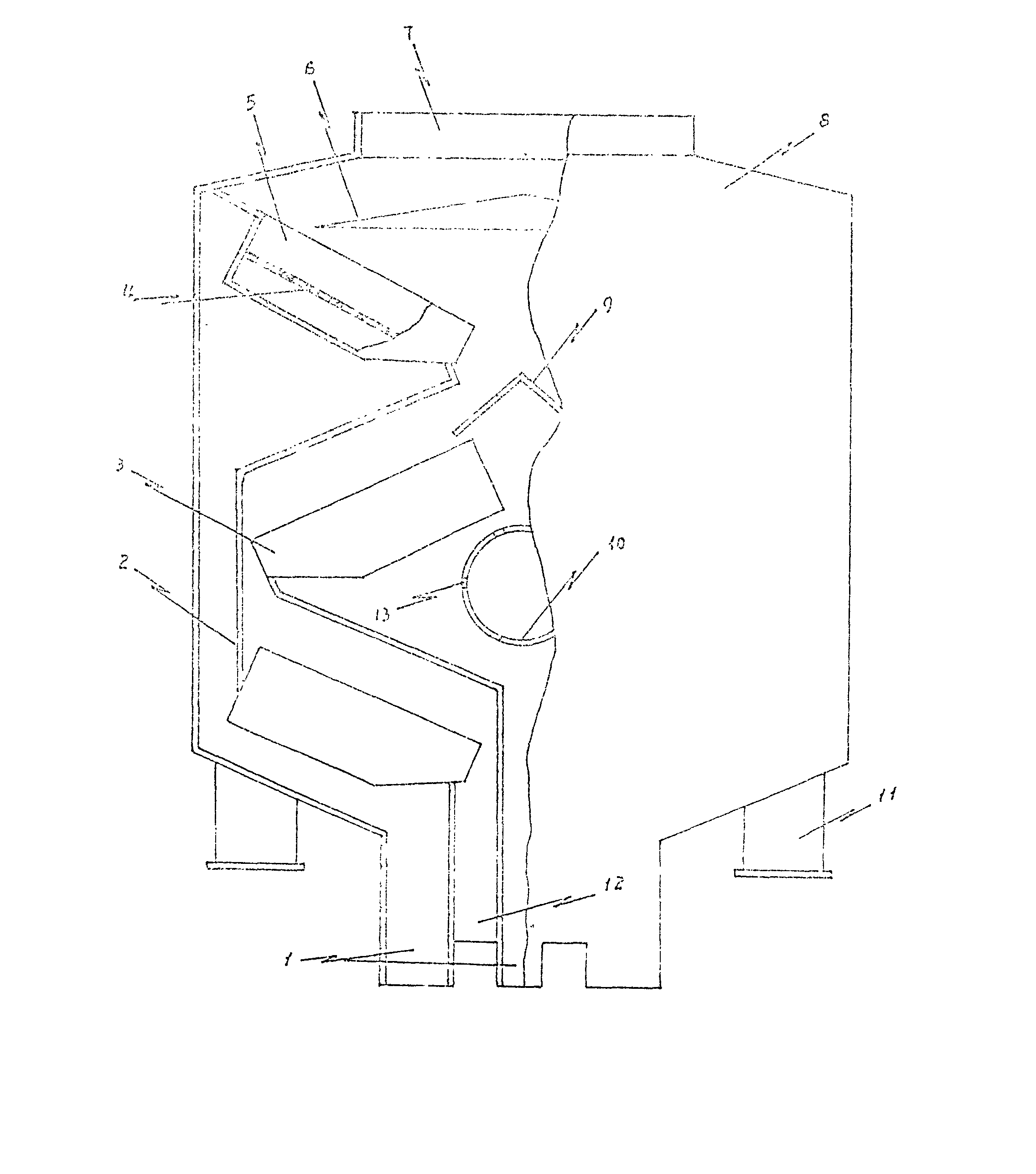
[0008] It can be seen from the accompanying drawings that the vibrating screen with less land occupation of this program mainly includes a feed inlet 7, an under-sieve material outlet 1, an over-sieve material outlet 12, a distributor 6, and a sieve plate 5 and a sieve surface 4. The sieve box 8 of a plurality of unit sieves 3 formed, and the excitation source 11 connected with the sieve box 8, this scheme is that the described plurality of unit sieves 3 are arranged up and down in the sieve box 8, and the tail and head Relative to the Z-shaped arrangement from top to bottom, the unit sieves 3 can be one group arranged up and down, or multiple groups arranged up and down. In this specific embodiment, three unit sieves 3 are arranged up and down as one There are two groups arranged corresponding to each other, and there is a par...


PUM


Abstract

The vibrating sieve includes sieve box of several sieve units, each of which has material feeding port, screening outlet, oversize material outlet, distributor, sieve plate and sieve surface, and vibrating source connected to the sieve box. The present invention features that the sieve units inside the sieve box are zigzag arranged from top to bottom through head-to-tail connection. There may be several sieve boxes and the oversize material and the screenings between different sieve units are separated with partition board. There may be material separation board and aspiration channel with aspiration port inside the sieve box. The method of the present invention can reduce the area covered by the vibrating sieve effectively without affecting sieving efficiency and precision.

Description

Technical field: [0001] The invention relates to a vibrating sieve for screening materials, in particular to a vibrating sieve occupying less land. Background technique: [0002] Vibrating screens in the prior art are generally installed end-to-end in a row. Therefore, the required land occupation for equipment installation is extremely large, which increases equipment investment and costs. Especially when renovating old equipment, there is very little space to install the vibrating screen. If the installation method of the vibrating screen is not improved, the equipment remodeling will not be possible. Invention content: [0003] The purpose of the present invention is to provide a vibrating screen technical solution with a small footprint, which can make the required space for installing the vibrating screen very small. [0004] This program is realized through the following technical measures. It mainly includes a sieve box with a feed inlet, a sieve material outlet, ...

Claims


Application Information

Patent Timeline
Patent Type & Authority Patents(China)
IPC IPC(8): B07B1/28
Inventor 孙功民孟祥义马秀娟
Owner 孙功民
Learn More