
Mechanical vehicle ray camera testing systems

A radiographic and detection system technology, applied in the field of radiographic detection, can solve the problems of units such as modulators with heavy weight, frequent plugging and unplugging, difficult operation, etc., achieve large detection range and detection ability, reduce dependence on site conditions, and adapt to the environment good sex effect

Inactive Publication Date: 2005-01-12
TSINGHUA UNIV +1
View PDF0 Cites 0 Cited by
  • Summary
  • Abstract
  • Description
  • Claims
  • Application Information

AI Technical Summary

Problems solved by technology

This method has the following disadvantages: 1) Some units such as modulators and power supplies are heavy and cannot be further disassembled, making it inconvenient to assemble and disassemble; 2) The electrical, gas, and water connection devices between each unit are frequently plugged in and out, which reduces the system quality. Reliability of work; 3) It takes a long time to load, unload and assemble the equipment on site, which cannot meet the needs of emergency situations, and also increases the probability of equipment damage; 4) There is no accelerator head position adjustment device, and it is difficult to change it when it is used on site Accelerator head position and orientation
Especially when detecting large and immovable equipment that has been installed on site, changing a detection position requires re-arrangement of system equipment, low detection efficiency and difficult operation

Method used


Image

  • Mechanical vehicle ray camera testing systems
  • Mechanical vehicle ray camera testing systems
  • Mechanical vehicle ray camera testing systems

Examples


Embodiment approach 1

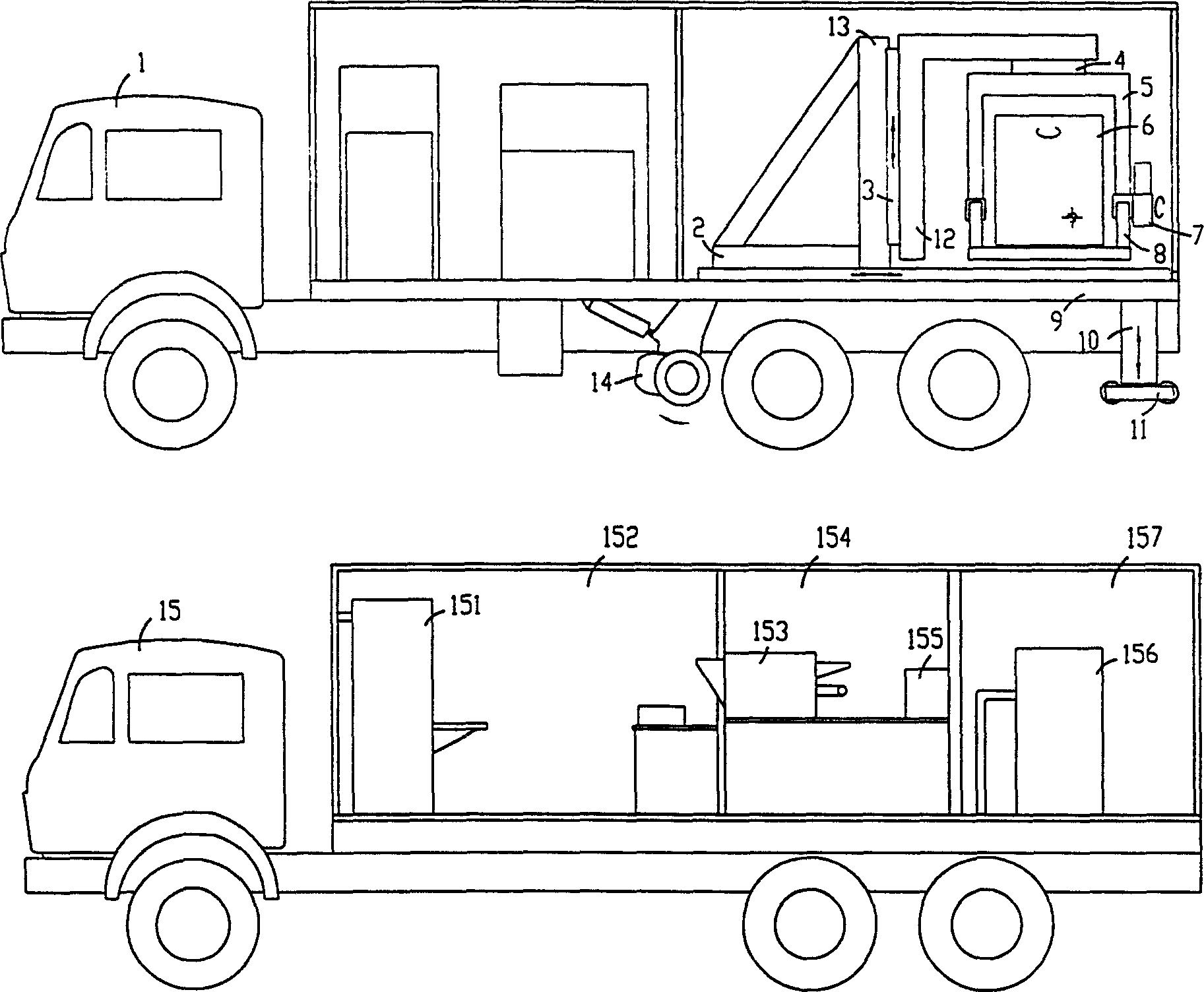
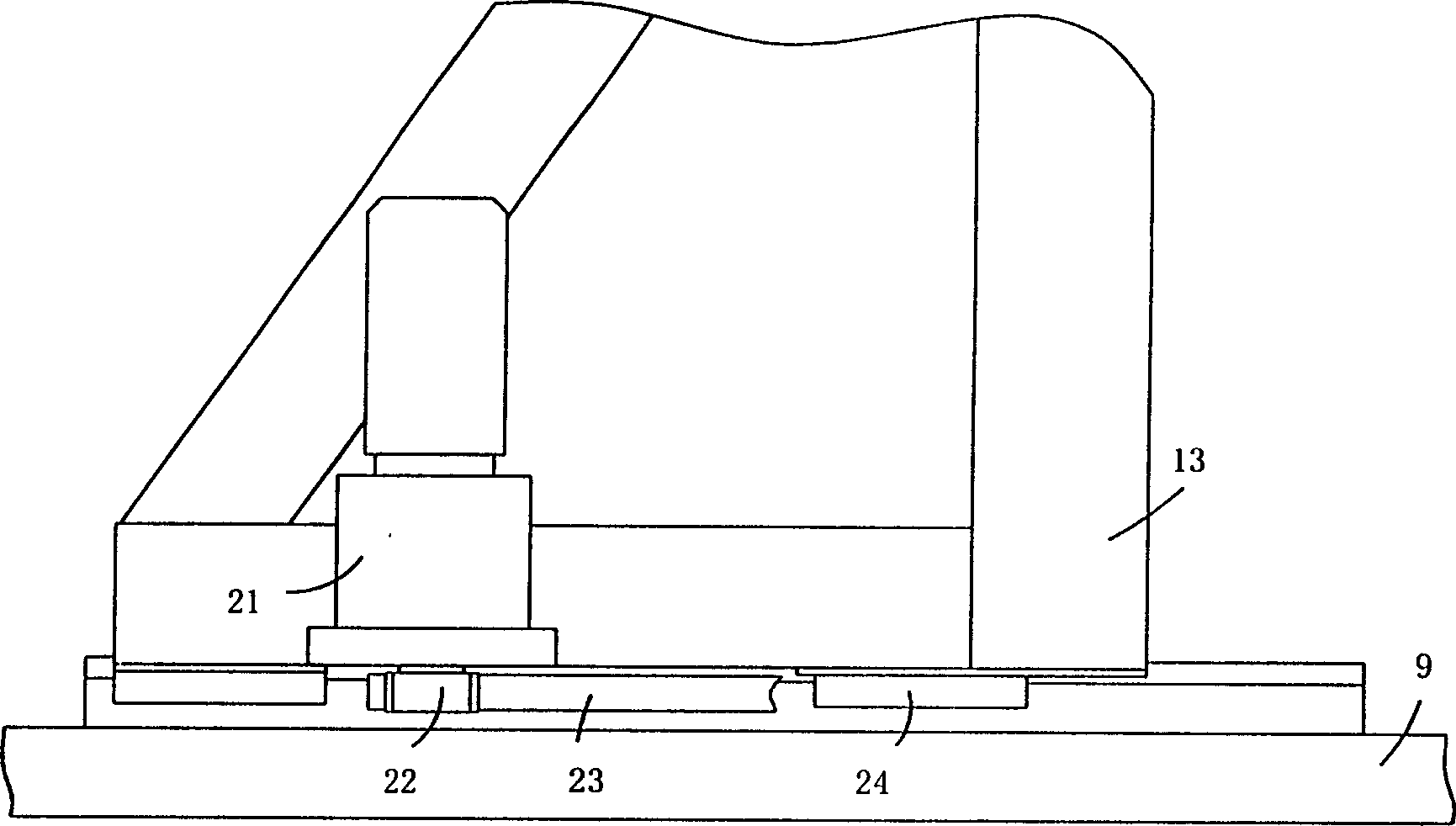
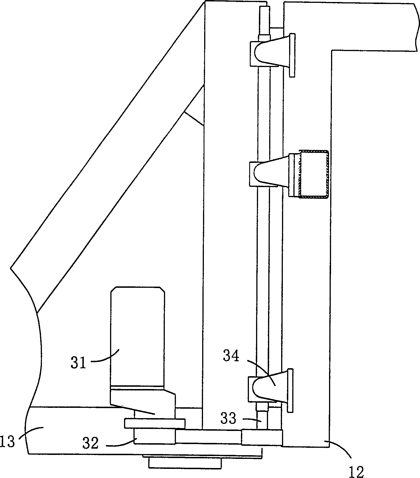
[0025] see figure 1 , the vehicle-mounted mobile radiography detection system includes an accelerator 6 , a detection vehicle 1 and a control vehicle 15 . The ancillary equipment of the accelerator and the control equipment of the system are arranged in the front cabin of the inspection vehicle 1 . A bracket 9 is arranged in the back compartment of the inspection vehicle 1, and the telescopic device 2 is installed on the bracket 9 to make the mobile frame made up of the fixed mount 13 and the frame 12 move back and forth horizontally. A lifting device 3 is installed between the fixed frame 13 and the frame 12 to make the frame 12 move up and down. A support consisting of an upper support 5 and a lower support 8 is installed in the frame 12. A rotating device 4 is installed between the end face of the frame 12 and the upper support 5 to make the support rotate as a whole. An accelerator 6 is installed on the lower support 8, and the upper support 5 and the lower support 8 is ...

Embodiment approach 2

[0037] When light-weight radioactive sources such as small electron accelerators, X-ray machines or gamma sources are used, the previously mentioned contraction device may not be installed on the inspection vehicle. Other implementations are the same as the first implementation.

Embodiment approach 3

[0039] This embodiment is basically the same as the first embodiment, except that the control car is removed. The control equipment on the aforementioned control vehicle is stored on the testing vehicle, and taken out from the testing vehicle when in use, the operation of the remote control accelerator, and the equipment layout on the testing vehicle are the same as those in Embodiment 1.


PUM


Abstract

A system includes detection vehicle which is equipped with telescoping device on carriage to enable movable frame built by holder and rack to make horizontal movement, equipped with lifting device in between the holder and rack to enable the rack to make up and down movement, equipped with rotary device in between the rack and up-support to enable the whole support built by up and down supports in the rack to make rotation movement and equipped with accelerator as well as tilting device on the down support, various position and gesture can be realized by the above devices when workpiece is detected by the accelerator, and control vehicle which is equipped with power, control and film processing equipment.

Description

technical field [0001] The invention relates to a vehicle-mounted mobile radiographic detection system using an electron accelerator as a radiation source, and belongs to the technical field of radiation detection. It is mainly used for on-site detection of large workpieces, such as pressure vessels, pipelines, bridges and important buildings. Background technique [0002] Existing mobile radiography equipment using electron accelerators as radiation sources is mainly realized by decomposing the detection system into multiple units and packaging and transporting them separately. This method has the following disadvantages: 1) Some units such as modulators and power supplies are heavy and cannot be further disassembled, making it inconvenient to assemble and disassemble; 2) The electrical, gas, and water connection devices between each unit are frequently plugged in and out, which reduces the system quality. Reliability of work; 3) It takes a long time to load, unload and as...

Claims


Application Information

Patent Timeline
Patent Type & Authority Patents(China)
IPC IPC(8): G01N23/04G01N23/083
Inventor 康克军高文焕江南王甲绪李元景刘以农李荐民陈志强李君利唐传祥刘耀红谢瑛王东宇
Owner TSINGHUA UNIV
Learn More