Temporary device identifier message informing method

A technology of a device identifier and a communication method, applied in the field of wireless communication devices, can solve problems such as time and energy consumption, and achieve the effects of reducing monitoring time, reducing function consumption, and eliminating time and energy

Inactive Publication Date: 2005-04-20
PACIFIC COMM SCI
View PDF1 Cites 0 Cited by
  • Summary
  • Abstract
  • Description
  • Claims
  • Application Information

AI Technical Summary

Problems solved by technology

In normal CDPD, considerable time and ener

Method used


Image

  • Temporary device identifier message informing method
  • Temporary device identifier message informing method
  • Temporary device identifier message informing method

Examples


Embodiment Construction

[0074] FIG. 6 is a time flow diagram illustrating a message block configuration that facilitates increased battery life through reduced power application in accordance with the present invention. As with most CDPD functions, the timing configuration shown in Figure 6 is generated in MD-IS using the Mobile Data Link Protocol (MDLP) described in Section 403 of the CDPD Specification Version 1.1. As previously discussed, operations and timing adjustments at the MDLP level are insufficient to achieve satisfactory reliability due to variance at the Medium Access Control (MAC) level (as specified in section 402 of the CDPD specification version 1.1). This disadvantage is thus overcome by the approach described below.

[0075] The invention is applicable to both the two-way paging variant of the CDPD system as well as the conventional scheme. This two-way paging variant is basically the same as the standard CDPD system, with a number of changes to enable two-way paging, as described...


PUM


Abstract

Energy expenditure is reduced in a wireless subscriber station operating in a Cellular Digital Packet Data (CDPD) system by deleting the operation of decoding the Forward Error Correction (FEC) blocks (69). The decoding of the FEC blocks can be deleted by virtue of using opening and closing Temporary Equipment Identifier (TEI) messages having a minimum Hamming distance from all the other TEI messages (62). Base Error Rate (BER) is measured to determine when the necessity of decoding an FEC block exists.

Description

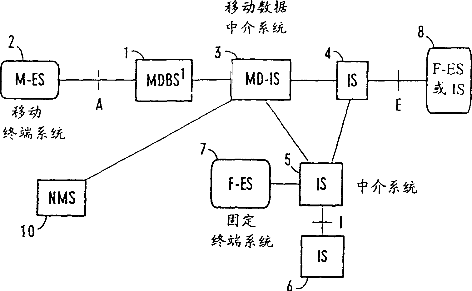
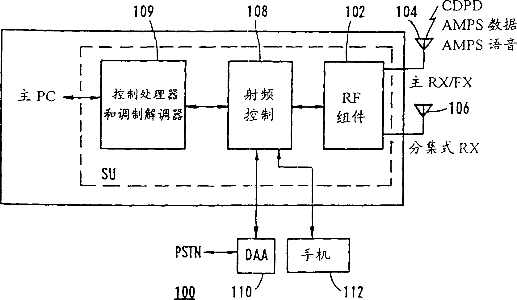
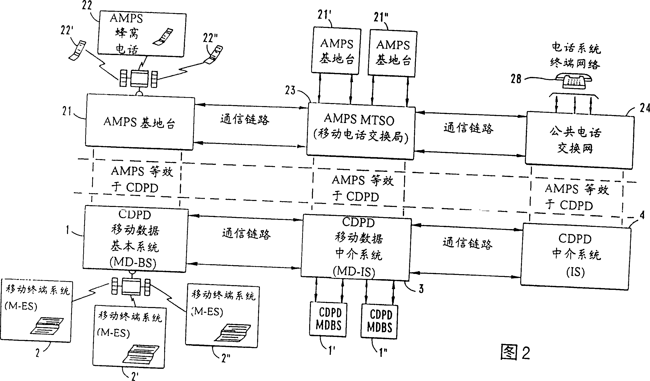
[0001] This application is a divisional application of the invention patent application with the application number 96197181.9 and the filing date of September 24, 1996, and the title is "Message Notification Method for Temporary Equipment Identifier". [0002] This application is a continuation of US Patent Application Serial No. 08 / 533,152, filed September 25,1995. technical field [0003] The present invention relates to wireless communication devices. More particularly, it relates to controlling the scanning operation of a wireless subscriber station to limit power consumption and extend battery life for powering the wireless subscriber station. Background technique [0004] A modern analog cellular system for subscriber mobile wireless duplex voice transmission known as "Advanced Mobile Phone Service" (AMPS) uses FCC-specified carrier frequencies in the range of 800-900 MHz. Vehicle cellular telephones transmit voice signals to cellular base stations within a given net...

Claims


Application Information

Patent Timeline
IPC IPC(8): H04Q7/20H04B7/26H04B1/16H04L1/00H04W52/02H04W76/04
CPCH04L1/0057H04W52/0229Y02D30/70
Inventor 卡尔·托马斯·哈汀詹姆斯·E·潘特拉诺维奇库马·巴拉乔君安德鲁·怀特
Owner PACIFIC COMM SCI
Why Eureka
Try Eureka