Metal cutting tool

A metal cutting and tool technology, applied in metal processing equipment, manufacturing tools, milling cutting inserts, etc., to achieve the effect of improving metal cutting efficiency and simplifying design

Inactive Publication Date: 2005-04-27
WALTER AG
View PDF0 Cites 3 Cited by
  • Summary
  • Abstract
  • Description
  • Claims
  • Application Information

AI Technical Summary

Problems solved by technology

This makes it nearly impossible to manufacture tools with more than one end cutting edge (for example, with four cutting discs to produce two end cutting edges)

Method used


Image

  • Metal cutting tool
  • Metal cutting tool
  • Metal cutting tool

Examples


Embodiment Construction

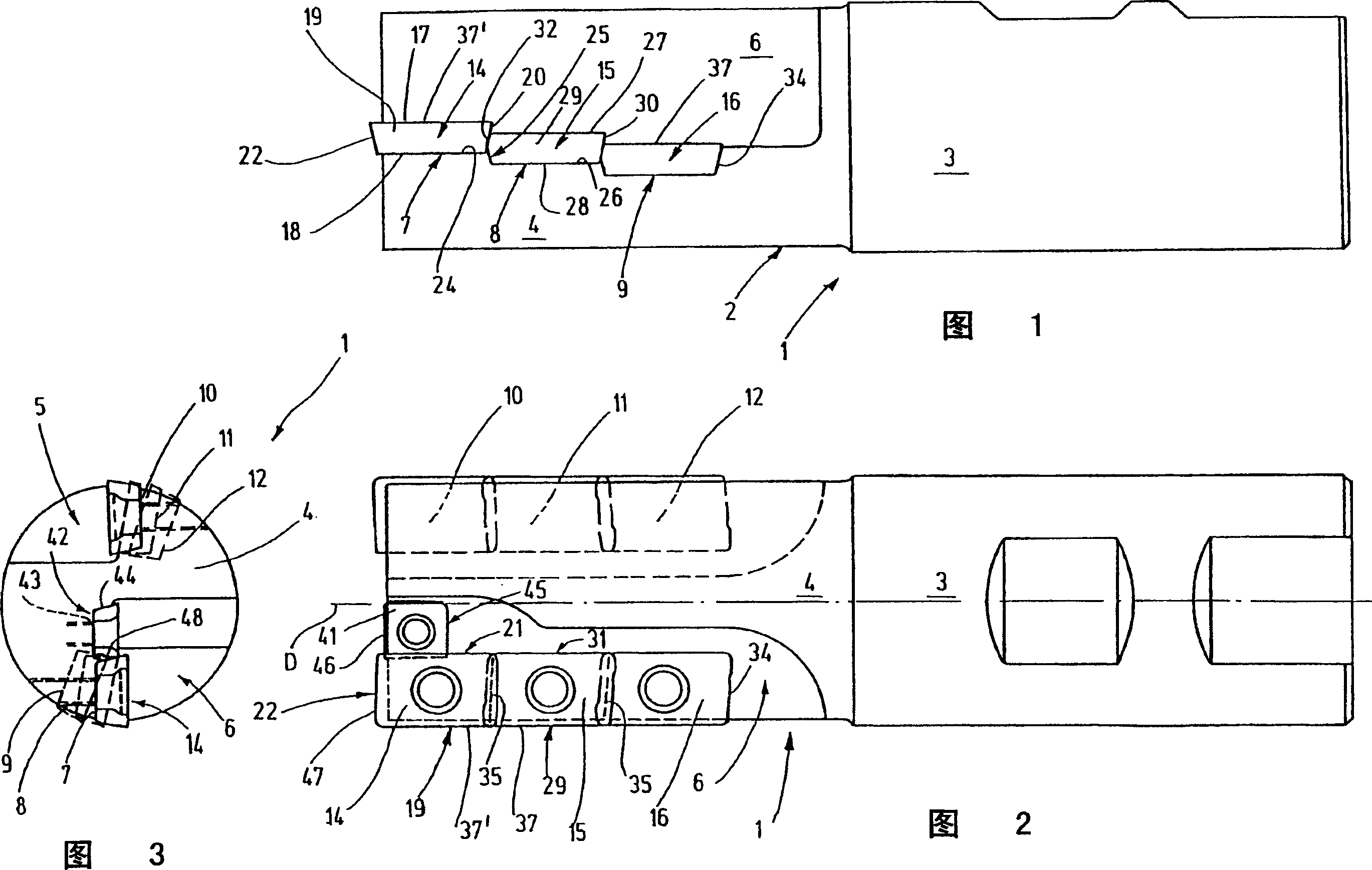
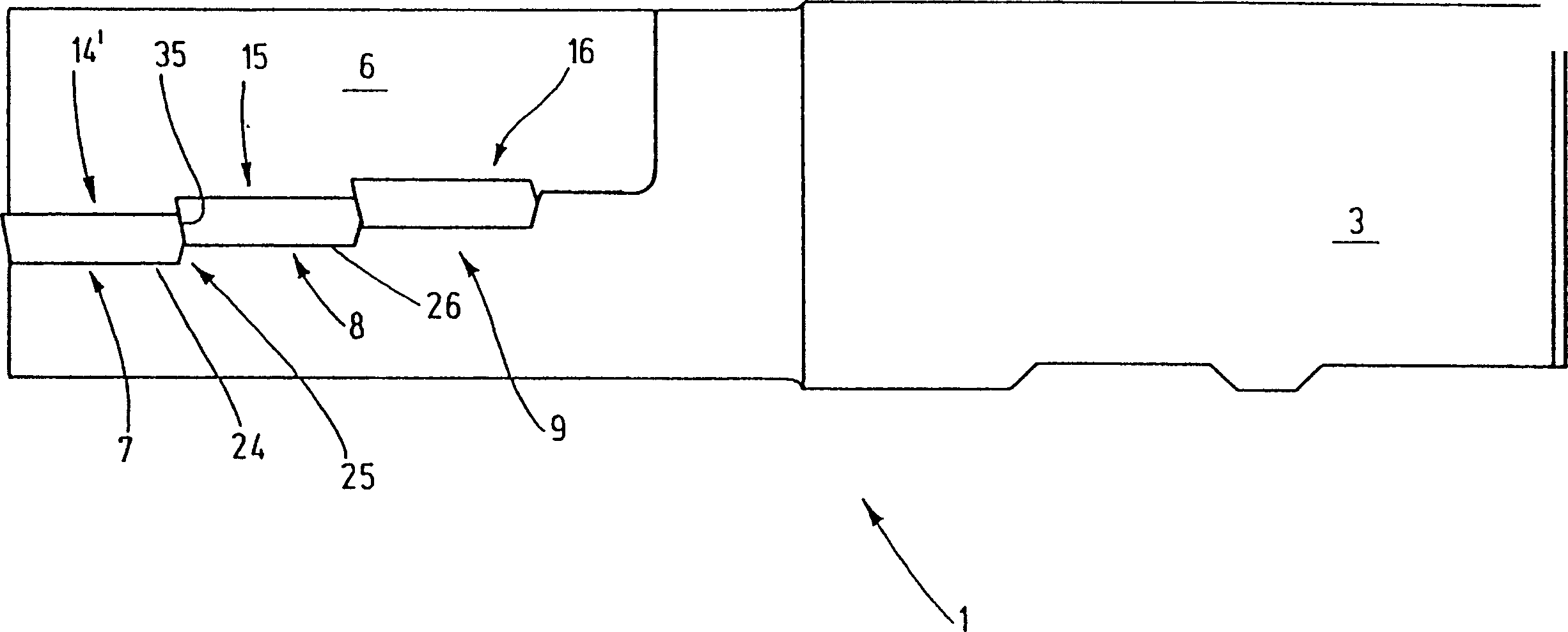
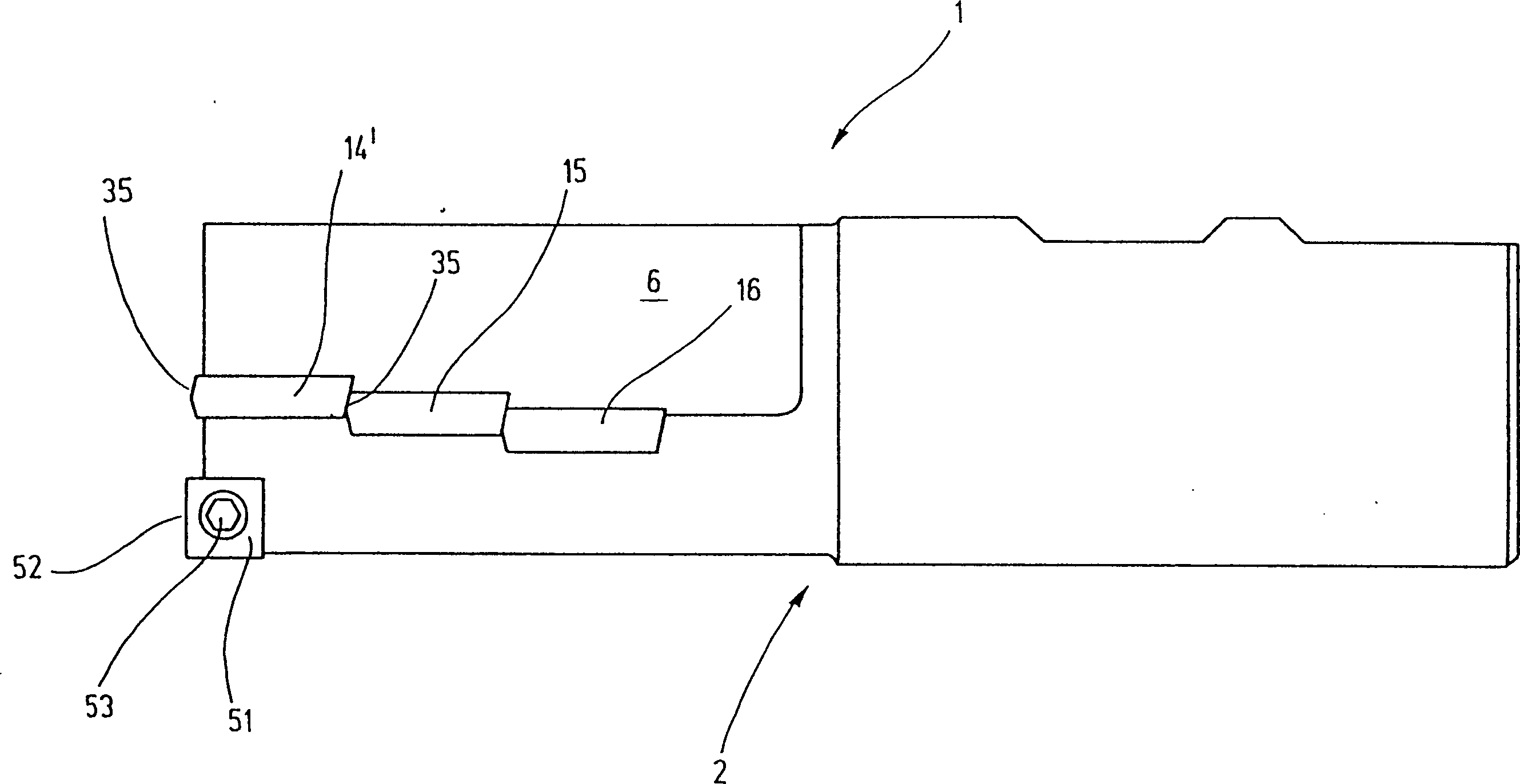
[0025] As shown in FIG. 1 , a metal cutting tool 1 has a tool body 2 with a clamping element 3 and a cutting disk support portion 4 . The support part is based on a substantially cylindrical base and has several chip flutes, for example two chip flutes 5 , 6 in the exemplary embodiment, which can be seen in FIG. 3 . Each chip flute 5 , 6 is an axially extending groove in which several disk seats 7 , 8 , 9 or 10 , 11 , 12 are arranged.

[0026] The chip flutes 5 , 6 or their disc seats 7 , 8 , 9 or 10 , 11 , 12 are identical and are preferably arranged symmetrically with respect to the axis of rotation D of the tool body 2 . Therefore, the following description of disc bases 7 , 8 , 9 also applies to disc bases 10 , 11 , 12 .

[0027] Disc holders 7 , 8 , 9 serve to hold cutting discs 14 , 15 , 16 . These square or rectangular or parallelogram cutting discs each have an end face 17, a base 18 and several transverse surfaces 19, 20, 21, 22 or 29, 30, 31, 32 (see FIGS. 1 and 2)...


PUM


Abstract

At least two cutting plates are provided for a metal cutting tool, particularly adopted for milling work, which are in direct contact with each other and therefore support each other. A particularly simple design of a plate seat may be used for a plurality of teeth with the cutting plates of a single chip groove in direct contact with each other for permitting a large metal cutting output.

Description

technical field [0001] The present invention relates to a metal cutting tool, and more particularly, the present invention relates to a metal cutting tool configured to process a workpiece by milling or drilling. Background technique [0002] What is used is a metal cutting tool for machining a workpiece by cutting, which has a tool body and several detachable cutting discs fastened thereto. Typically, cutting discs are replaceable and have greater hardness and wear resistance. The tool body in turn holds and guides the cutting disc in the appropriate disc seat. The length of the cutting edge that is commonly used in cutting operations is greater than the length of a single cutting disc. In this case, the desired cutting edge is combined with the cutting edges of several cutting discs arranged on the tool body such that each cutting edge slightly overlaps the other cutting edge in the circumferential direction. [0003] Especially with regard to peripheral milling tools, ...

Claims


Application Information

Patent Timeline
Patent Type & Authority Patents(China)
IPC IPC(8): B23B51/00B23C5/10B23C5/22B23C5/00
CPCB23C2200/125B23C5/109B23C5/2221Y10T409/30784Y10T407/1966Y10T409/30Y10T407/191B23C5/2213B23C5/10
Inventor S·维拉
Owner WALTER AG
Why Eureka
Try Eureka