Submersible transformer using device with circuit braker and fuse for self-protecting

A technology of transformers and fuses, which is applied in the direction of transformers, fixed transformers, parts of protective switches, etc., can solve problems such as the inability to consider bushings or short circuits between bushings and circuit breakers, and reduce the risk of failure, performance and cost Favorable, good electrical insulation effect

Inactive Publication Date: 2005-06-15
SCHNEIDER ELECTRIC IND SAS
View PDF4 Cites 0 Cited by
  • Summary
  • Abstract
  • Description
  • Claims
  • Application Information

AI Technical Summary

Problems solved by technology

Therefore, short circuits at the bushing or between the bushing and the circuit breaker cannot be considered

Method used


Image

  • Submersible transformer using device with circuit braker and fuse for self-protecting
  • Submersible transformer using device with circuit braker and fuse for self-protecting
  • Submersible transformer using device with circuit braker and fuse for self-protecting

Examples


Embodiment Construction

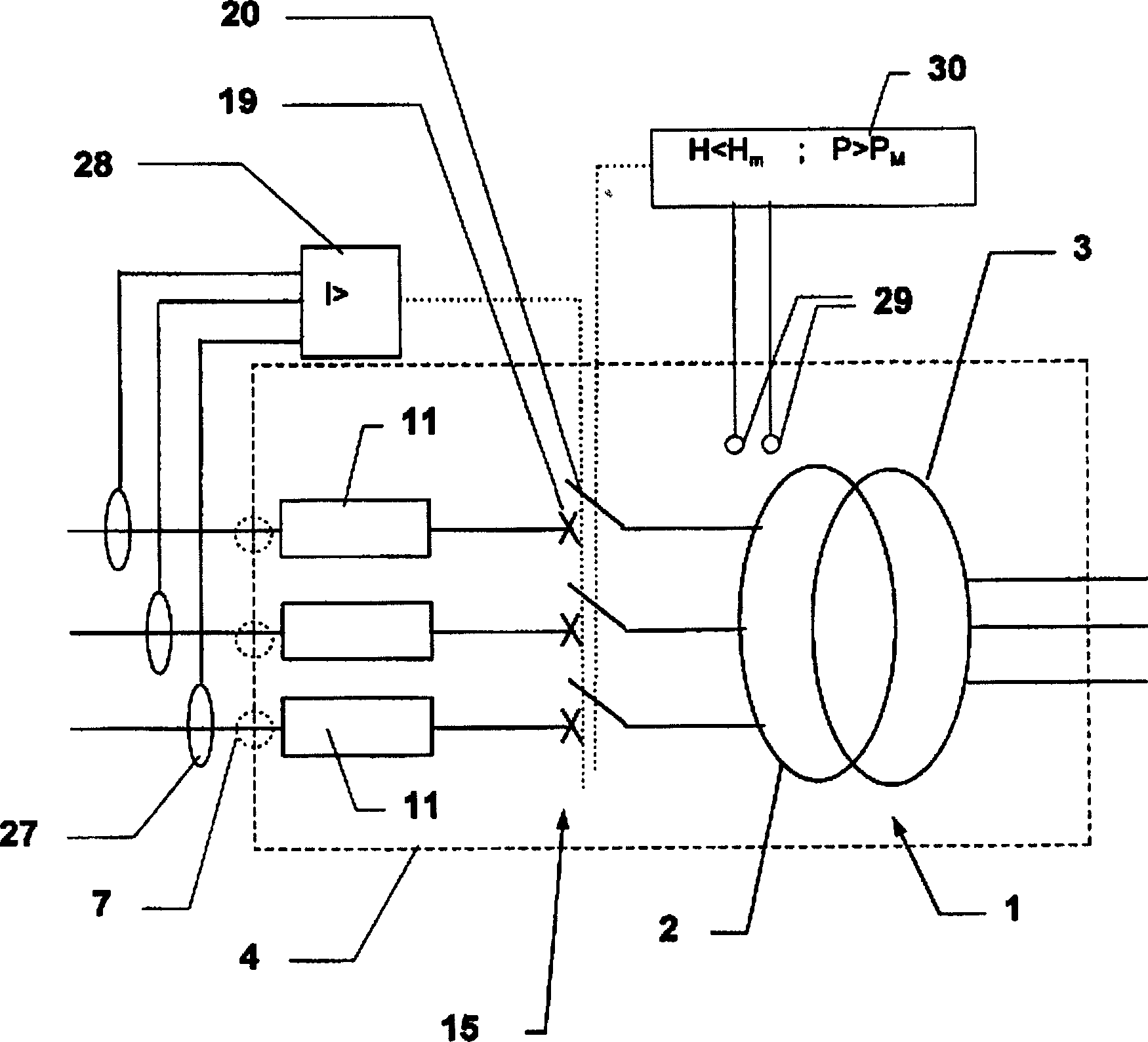
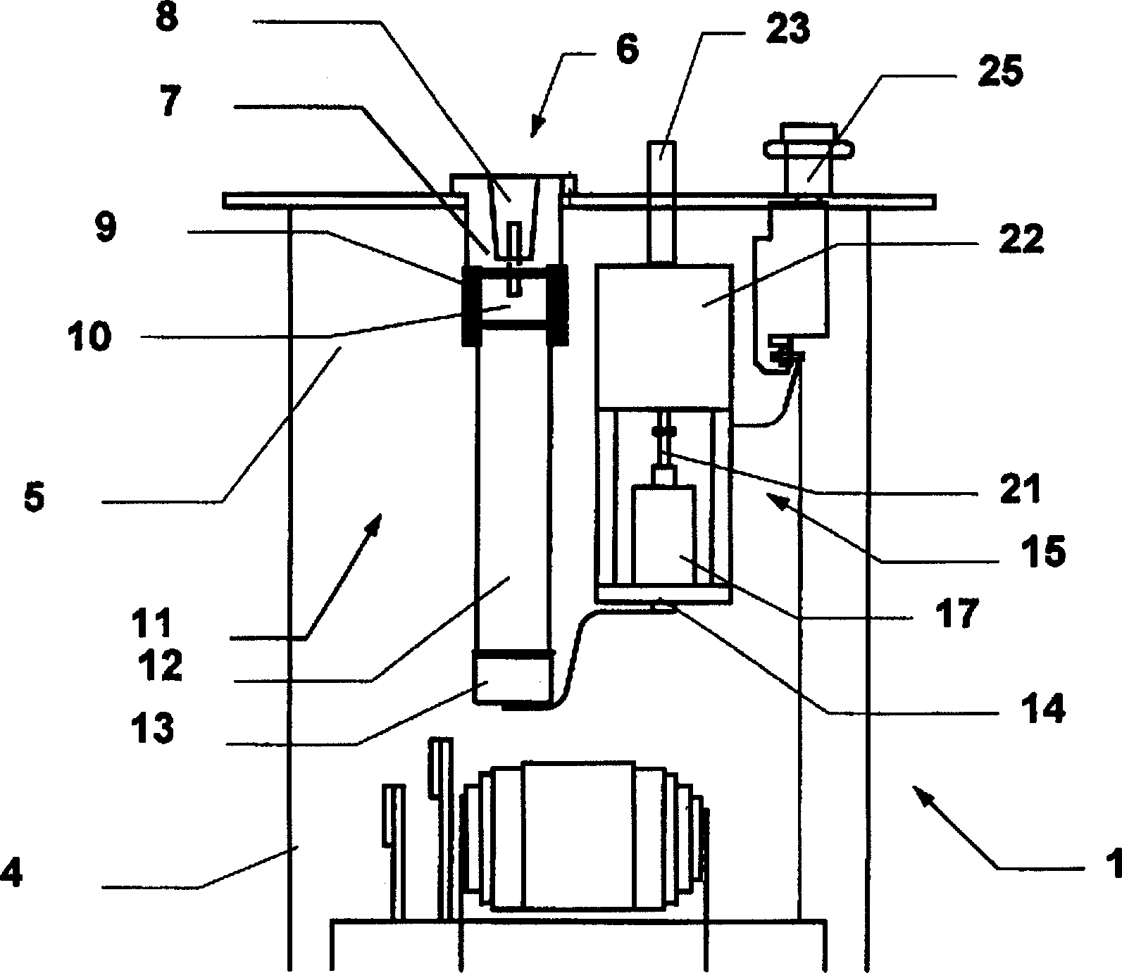
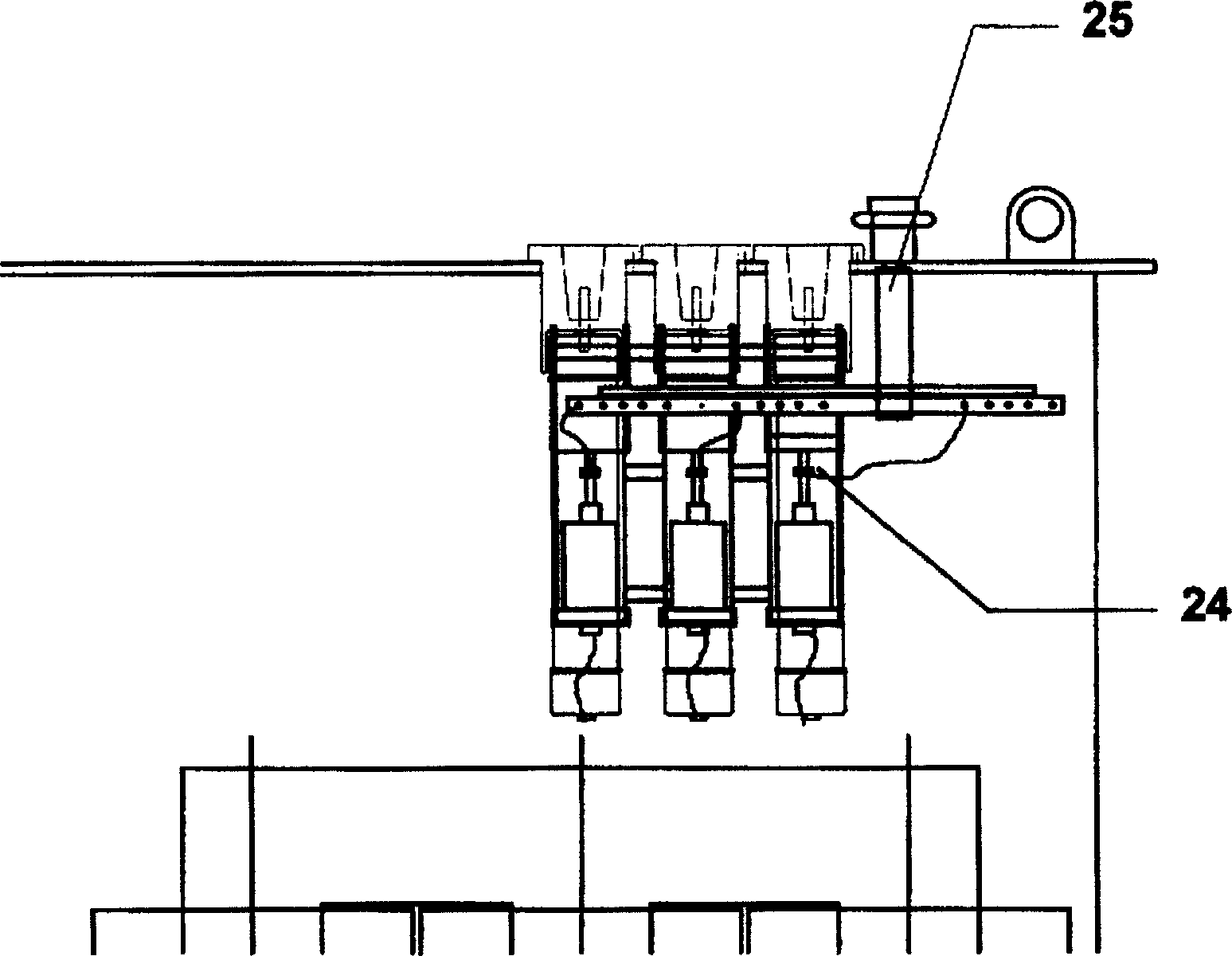
[0048] see Figure 1~3 , The three-phase medium and low voltage transformer 1 includes a primary winding 2 and a secondary winding 3 immersed in a tank 4, and the tank 4 is filled with a dielectric liquid 5, which may be oil. The phases of the primary circuit of the transformer extend into the box 4 through the multifunctional part 6 containing the medium voltage bushing 7 .

[0049] The multifunctional part 6 comprises a dedicated insertion area 8 on its outer part of the box 4 and an engagement area 9 for the head 10 of the fuse 11 on its inner part of the box 4 . The fuse 11 is a conventional confining fuse, the middle of which constitutes a body 12 with a cylindrical outer wall and insulation, and two metal ends, a head 10 and a root 13 . The engagement area 9 includes a tubular outer wall made of electrically insulating elastic rubber material, and its bottom end fits with the body 12 of the fuse 11 to realize the sealing between the fuse head 10 and the oil 5 . The top...


PUM


Abstract

A transformer includes a tank containing dielectrics in which are immersed the primary and secondary circuits and protective devices connected to the primary circuit and including circuit breakers controlled by tripping devices and fuses. The fuse is located between the box bushing and the circuit breaker. In the event of a short circuit at the terminals of the secondary circuit, the contacts of the circuit breaker separate and interrupt the current flow, and the fuses do not melt; the intensity of current flowing into each fuse has a threshold, which is lower than the breaking capacity of the corresponding pole of the circuit breaker, and above which, Before the contact arrangement separates, the fuse melts.

Description

technical field [0001] The invention relates to an electrical transformer, the windings and the magnetic circuit of which are immersed in a dielectric liquid or gas contained in a tank, and provided with protective devices designed to limit the effects of undesirable internal operation of the transformer. Background technique [0002] Document FR-A-2,712,730 describes a tank-immersed three-phase transformer of this type, the protection of which consists of a protective fuse for each phase between each supply phase and the corresponding primary winding of the transformer, and Three-phase disconnect switch located between the fuse and the corresponding transformer phase. The tripping device opens the circuit breaker according to the signal from the sensor. The sensor senses a change in at least one parameter representative of a property of the dielectric fluid. The measured parameter is the dielectric body pressure, which constitutes an indication of local malfunctions withi...

Claims


Application Information

Patent Timeline
IPC IPC(8): H01F27/00H01F27/40H01F30/00H02H7/04H01H85/00H01H71/10
CPCH01H71/1081H01F27/402H01H2085/0291
Inventor 雅克·怀尔德迪蒂尔·富奇龙克里斯托弗·普雷夫
Owner SCHNEIDER ELECTRIC IND SAS
Why Eureka
Try Eureka