35kv integrated photovoltaic combined transformer for photovoltaic power generation system

A photovoltaic power generation system and combined transformer technology, applied in the field of transformers, can solve problems such as difficult commissioning and maintenance, large space occupation, and accident-prone problems, and achieve the effects of unified commissioning and maintenance, small footprint, and perfect protection

Active Publication Date: 2019-04-16
SANBIAN SCI TECH
View PDF5 Cites 0 Cited by
  • Summary
  • Abstract
  • Description
  • Claims
  • Application Information

AI Technical Summary

Problems solved by technology

[0002] The step-up box transformer and inverter room of the traditional photovoltaic power generation system are designed separately, connected by underground cables, occupying a large space, prone to accidents, high investment costs, and difficult to debug and maintain

Method used


Image

  • 35kv integrated photovoltaic combined transformer for photovoltaic power generation system
  • 35kv integrated photovoltaic combined transformer for photovoltaic power generation system
  • 35kv integrated photovoltaic combined transformer for photovoltaic power generation system

Examples


Embodiment 1

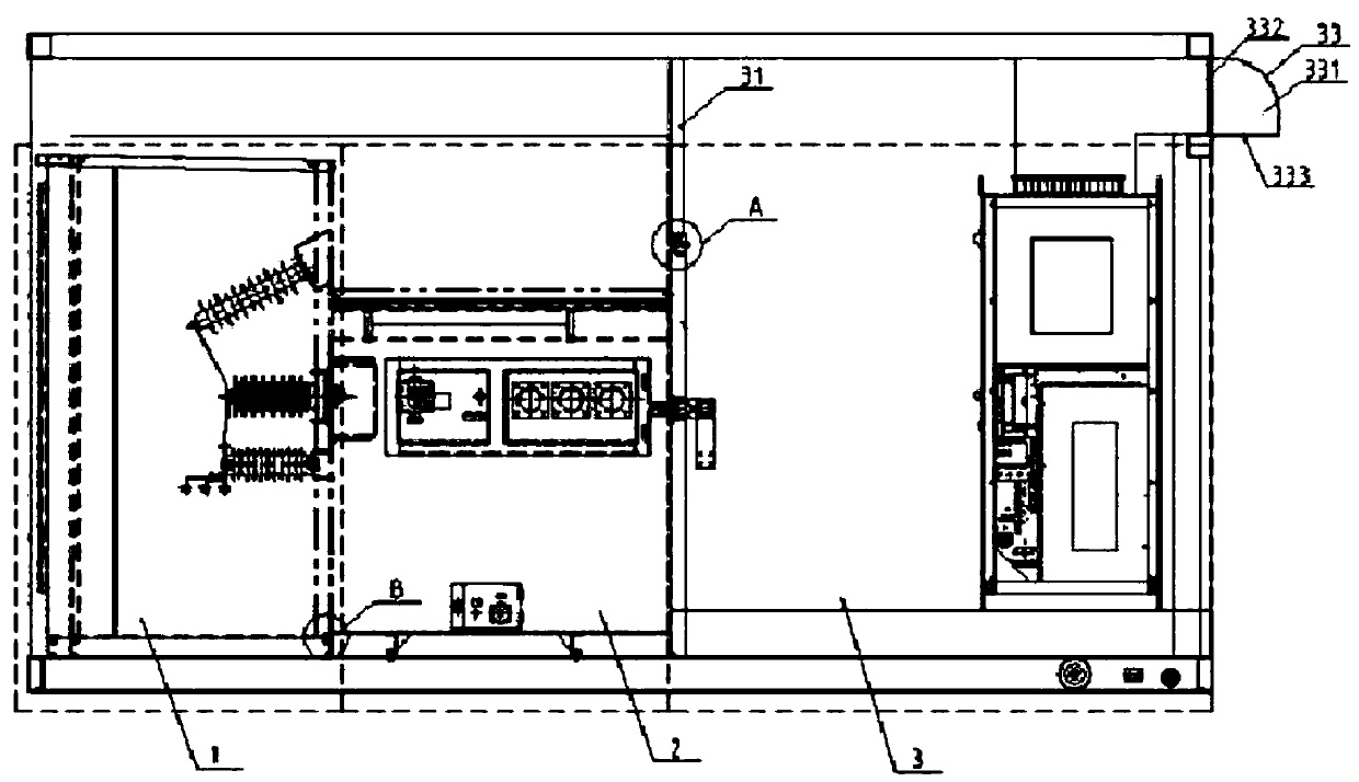
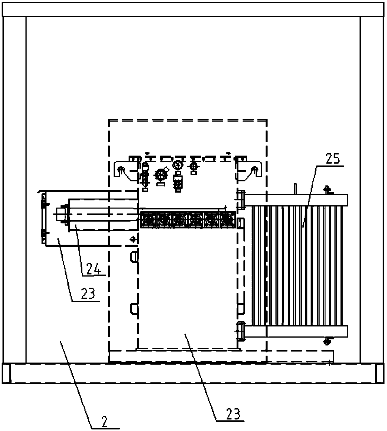
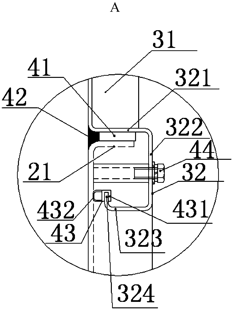
[0024] 35kV integrated photovoltaic combined transformer for photovoltaic power generation system, such as Figure 1-4 , including high voltage chamber 1, transformer chamber 2, and inverter chamber 3 from left to right; the side wall of inverter chamber 3 at the contact point with transformer chamber 2 is the side wall 31 with a gap in the middle, and the side wall of transformer chamber 2 Snap to the side wall 31 with a gap in the middle, the end of the side wall 31 with a gap in the middle is a U-shaped flange 32, the end of the wall of the transformer room 2 is provided with a transverse flange 21, and the side wall with a gap in the middle 31 and the side wall of the transformer chamber 2 are connected by U-shaped fold 32 and transverse fold 21; Vertical side 324, a sealing strip 41 and silicone glue 42 are provided between the first transverse side 321 and the transverse folded side 21, and a strip steel sealing strip 43 is provided between the second vertical side 324 a...

Embodiment 2

[0026] 35kV integrated photovoltaic combined transformer for photovoltaic power generation system, such as Figure 1-4 , including high voltage chamber 1, transformer chamber 2, and inverter chamber 3 from left to right; the side wall of the inverter chamber 3 in contact with the transformer chamber 2 is the side wall 31 with a gap in the middle, and the side wall of the transformer chamber 2 Snap to the side wall 31 with a gap in the middle, the end of the side wall 31 with a gap in the middle is a U-shaped flange 32, the end of the wall of the transformer room 2 is provided with a transverse flange 21, and the side wall with a gap in the middle 31 and the side wall of the transformer chamber 2 are connected by U-shaped fold 32 and transverse fold 21; Vertical side 324, a sealing strip 41 and silicone glue 42 are provided between the first transverse side 321 and the transverse folded side 21, and a strip steel sealing strip 43 is provided between the second vertical side 324...

Embodiment 3

[0029] 35kV integrated photovoltaic combined transformer for photovoltaic power generation system, such as Figure 1-4 , including high voltage chamber 1, transformer chamber 2, and inverter chamber 3 from left to right; the side wall of inverter chamber 3 at the contact point with transformer chamber 2 is the side wall 31 with a gap in the middle, and the side wall of transformer chamber 2 Snap to the side wall 31 with a gap in the middle, the end of the side wall 31 with a gap in the middle is a U-shaped flange 32, the end of the wall of the transformer room 2 is provided with a transverse flange 21, and the side wall with a gap in the middle 31 and the side wall of the transformer chamber 2 are connected by U-shaped fold 32 and transverse fold 21; Vertical side 324, a sealing strip 41 and silicone glue 42 are provided between the first transverse side 321 and the transverse folded side 21, and a strip steel sealing strip 43 is provided between the second vertical side 324 a...


PUM


Abstract

The invention relates to the technical field of transformers, and discloses a 35kV integrated photovoltaic combined transformer for a photovoltaic power generation system. The 35kV integrated photovoltaic combined transformer comprises, sequentially from left to right, a high-voltage chamber (1), a transformer chamber (2), and an inverter chamber (3). The sidewall, contacting the transformer chamber (2), of the inverter chamber (3) is a sidewall (31) with a gap in the middle. The sidewall of the transformer chamber (2) is clamped to the sidewall (31) with a gap in the middle. The structure advantage of the invention is that the transformer chamber and the inverter chamber are assembled as a whole. However, traditionally, the transformer chamber and the inverter chamber are connected by an underground cable, and main circuit breakers are additionally installed at the AC sides of a booster box substation and an inverter for effective protection. In the invention, the transformer chamber is taken as the rear wall of the inverter chamber, and the space is reduced greatly. The transformer chamber and the inverter chamber are connected by a copper bus, which is safe and reliable. The main circuit breaker of the booster box substation, the inverter chamber and the civil foundation can be omitted to achieve the effects of small area and lower cost of investment.

Description

technical field [0001] The invention relates to the technical field of transformers, in particular to a 35kV integrated photovoltaic combined transformer used in a photovoltaic power generation system. Background technique [0002] The step-up box transformer and inverter room of the traditional photovoltaic power generation system are designed separately, connected by underground cables, occupying a large space, prone to accidents, high investment costs, and difficult to debug and maintain. Contents of the invention [0003] Aiming at the shortcomings of the prior art, the present invention provides a 35kV integrated photovoltaic combined transformer for photovoltaic power generation systems; the transformer room and inverter room are changed to an integrated mode, which achieves small volume, compact structure, rapid deployment, Technical effects such as unified maintenance and cost reduction make the product function, temperature rise and protection level meet the stric...

Claims


Application Information

Patent Timeline
Patent Type & Authority Patents(China)
IPC IPC(8): H02B7/06H02B1/46H02B1/28H02B1/56
CPCH02B1/28H02B1/46H02B1/565H02B7/06
Inventor 徐秋元俞尚群王君钱陈益
Owner SANBIAN SCI TECH
Why Eureka
Try Eureka