Permanent magnet executor
A permanent magnet operation and permanent magnet technology, applied in the protection switch operation/release mechanism, the power device inside the switch, etc., can solve the problems of low overall reliability, complex structure, large energy storage noise, etc. The effect of maintenance, good matching performance and simple structure
- Summary
- Abstract
- Description
- Claims
- Application Information
AI Technical Summary
Problems solved by technology
Method used
Image
Examples
Embodiment 1
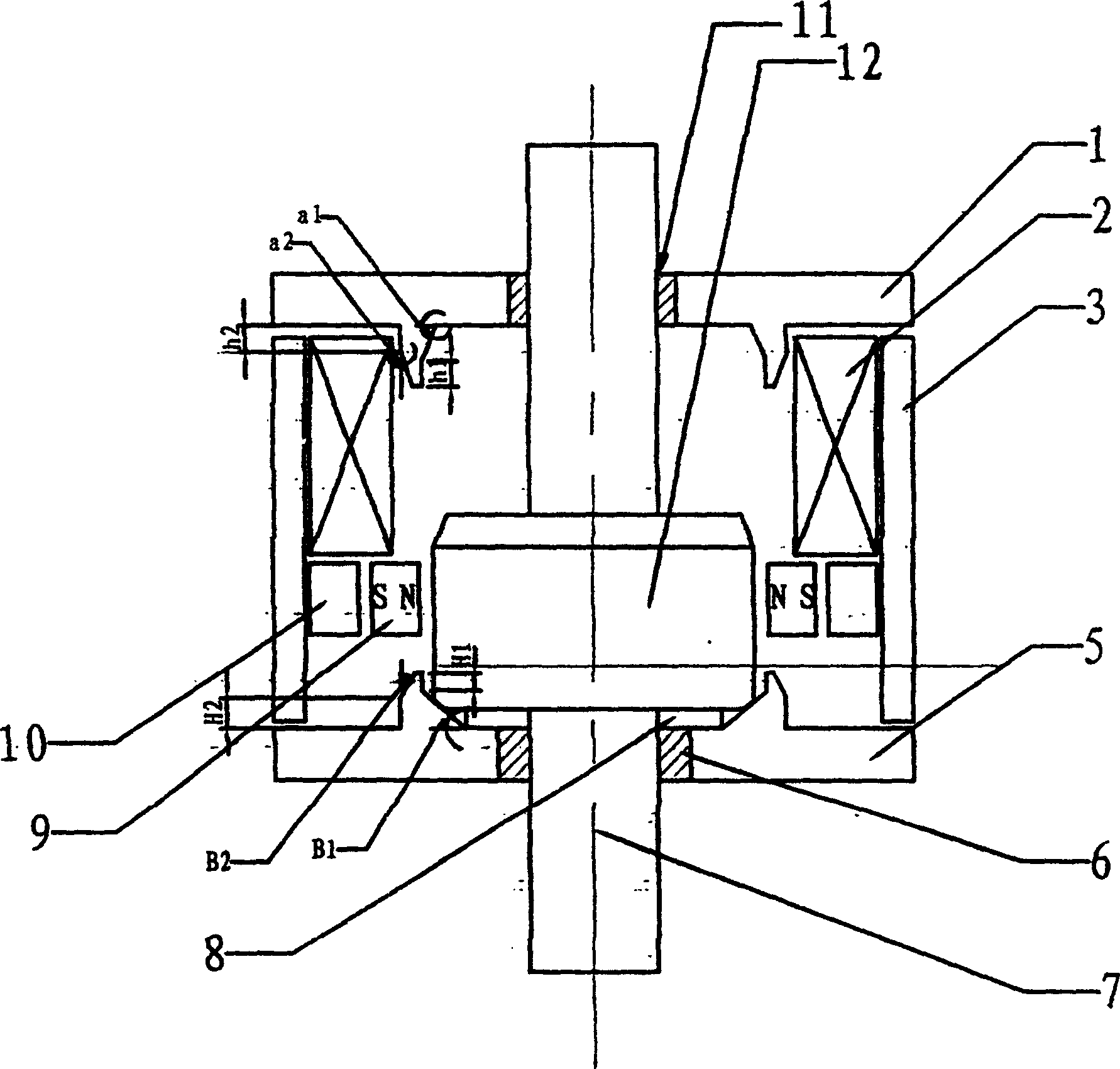
[0022] see figure 1 , figure 1 It is the first structure schematic diagram of the present invention.
[0023] According to the technical solution of the present invention, the permanent magnet mechanism includes: a transmission rod 7, an armature 12 is arranged on the transmission rod, the armature 12 is a cylinder, and its upper and lower ends have taper angles respectively, and the taper angle refers to the cylinder side facing the axis. The angle of center inclination; the opening coil, permanent magnet 9, pole shoe 10, closing coil 2 and static iron core 3 are respectively arranged around the armature 12, and the upper and lower ends of the transmission rod 7 pass through the upper and lower shaft sleeves , 6, the upper and lower bushings are respectively inlaid on the upper end cover 1 and the lower end cover 5, and an auxiliary gasket 8 is installed on the lower end cover 5. same angle.
[0024] The static iron core 3, the upper end cover 1 and the lower end cover 5 c...
Embodiment 2
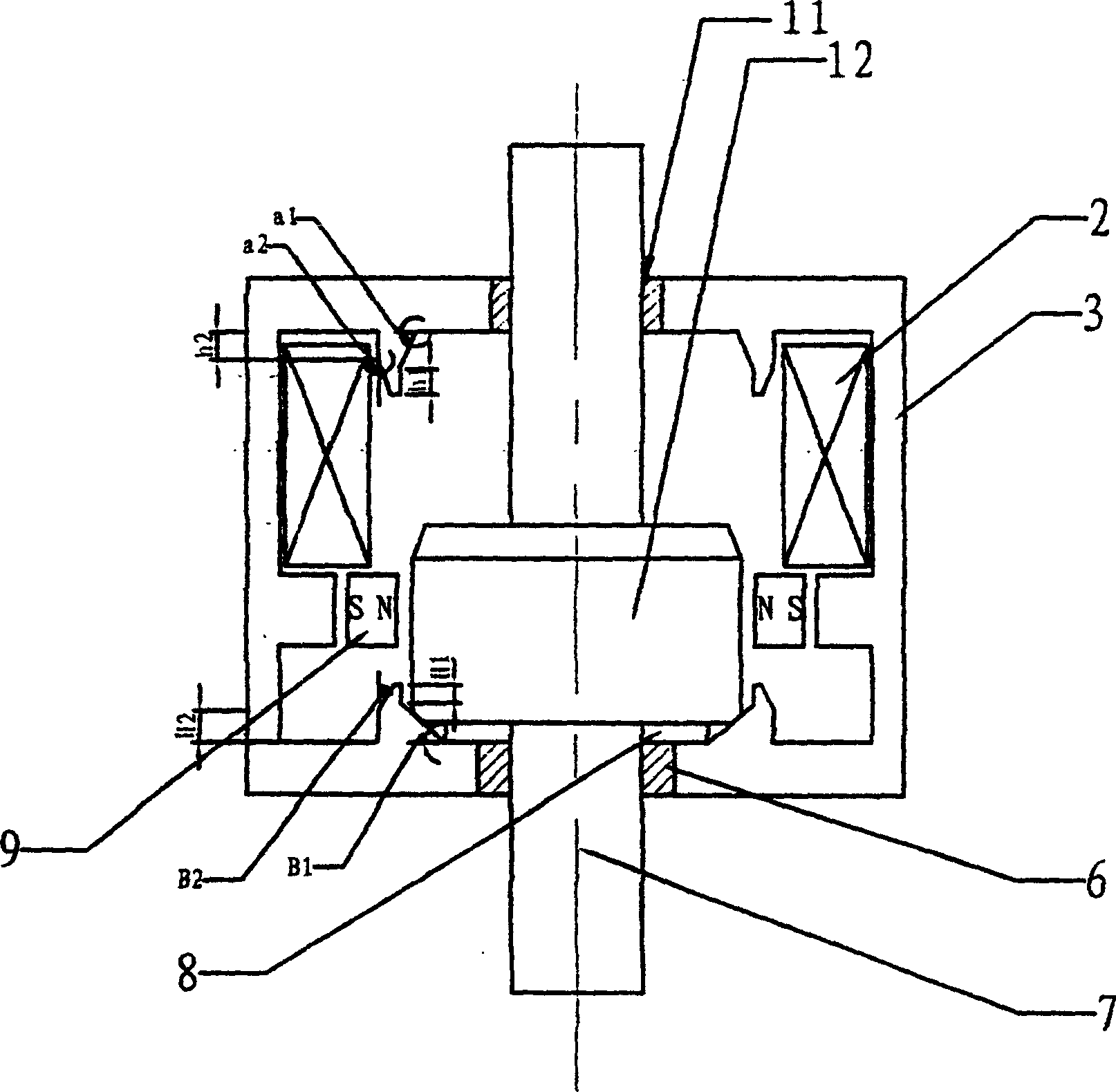
[0026] figure 2 It is the second structure schematic diagram of the present invention. The difference between this embodiment and Embodiment 1 is that this embodiment adopts a square structure. In the square structure, the upper and lower end covers 1, 5 and their attached basin shapes, the static iron core 3 and the pole shoe 10 are made into a whole, and are collectively called the static iron core. Simultaneously, the auxiliary gasket 8 and the armature 12 are also made into corresponding square shapes. All the other are with embodiment 1.
Embodiment 3
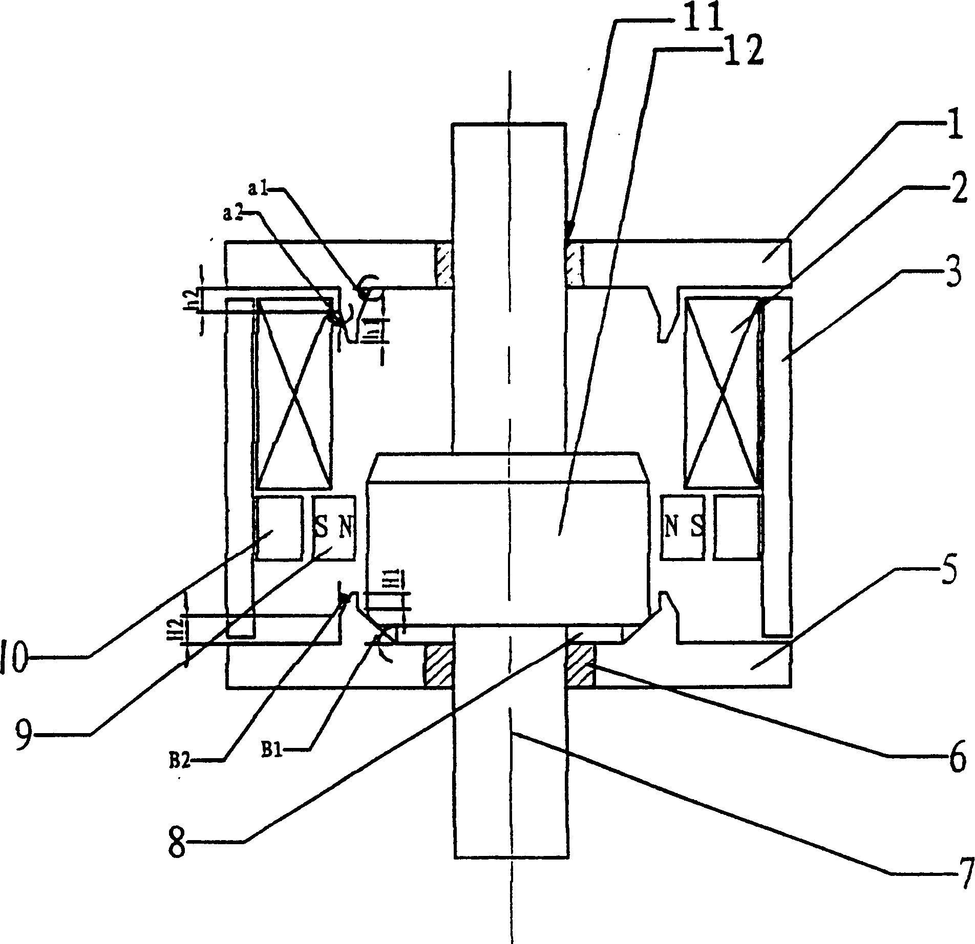
[0028] image 3 It is a schematic diagram of the third structure of the present invention. The difference between this embodiment and Embodiment 1 is that the opening coil is removed around the armature 12, and the rest are the same as in Embodiment 1. The current in the opposite direction of the gate current is used to complete the opening operation. However, this structure will produce a certain demagnetization effect on the permanent magnet, and the purpose of Embodiment 1 can also be achieved under certain less demanding conditions.
PUM
 Abstract
Description
Claims
Application Information
 - R&D
- Intellectual Property
- Life Sciences
- Materials
- Tech Scout
- Unparalleled Data Quality
- Higher Quality Content
- 60% Fewer Hallucinations
Browse by: Latest US Patents, China's latest patents, Technical Efficacy Thesaurus, Application Domain, Technology Topic, Popular Technical Reports.
© 2025 PatSnap. All rights reserved.Legal|Privacy policy|Modern Slavery Act Transparency Statement|Sitemap|About US| Contact US: help@patsnap.com


