Medium flow speed measurement sensor

A flow velocity measurement and sensor technology, which is applied in the field of measurement sensors, can solve the problems of increasing pipeline pressure difference, difficulty in processing and forming, complex structure, etc., and achieves the effects of low cost, simple structure, and improved measurement accuracy and sensitivity

Inactive Publication Date: 2005-06-22
江苏环能工程有限公司
View PDF1 Cites 0 Cited by
  • Summary
  • Abstract
  • Description
  • Claims
  • Application Information

AI Technical Summary

Problems solved by technology

It only improves the measurement accuracy from external factors, but does not essentially increase the pressure difference generated in the pipeline to improve the measurement accuracy, and the structure is complex. In order to ensure the ellipticity of the elbow, it is difficult to process and shape

Method used


Image

  • Medium flow speed measurement sensor
  • Medium flow speed measurement sensor
  • Medium flow speed measurement sensor

Examples


Embodiment Construction

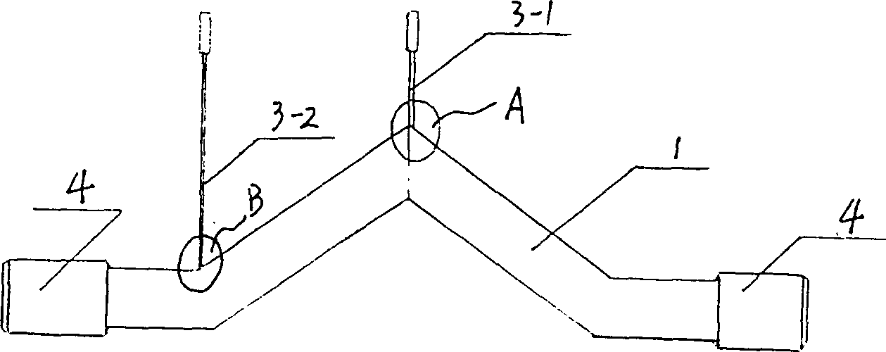
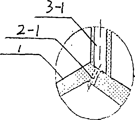
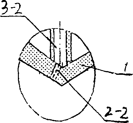
[0014] figure 1 The illustrated embodiment 1 of the present invention includes a pipeline 1 with a circular cross section, high and low pressure pressure introduction holes 2-1, 2-2 and high and low pressure pressure introduction pipes 3-1, 3-2, and the two ends of the pipeline 1 There is also a pipe joint 4, wherein the axis of the pipeline 1 is folded in three to form a V shape, the low-pressure pressure introduction hole 2-2 is arranged inside the first corner of the pipeline wall, the low-pressure pressure introduction pipe 3-2 is fixedly connected with the pipeline 1, and the high-pressure pressure introduction hole 2-1 is arranged outside the second corner of the pipe wall, and the high-pressure pressure induction pipe 3-1 is fixedly connected with the pipe 1. The low pressure and high pressure of the medium respectively pass through the low pressure pressure hole 2-2 and the high pressure pressure hole 2-1, and then pass through the low pressure pressure pipe 3-2 and th...


PUM


Abstract

The invention relates to a sensor for measuring the flow rate of a medium, which includes a pipeline passing through the medium, high and low pressure pressure introduction holes, and high and low pressure pressure introduction pipes, which are used to connect the pressure difference outlet pipe of the flow rate of the reaction medium with a pressure difference transmitter; The central line of the pipeline has at least one bend, which can change the flow direction of the medium; the high and low pressure pressure introduction holes are arranged at any corner of the pipeline wall, and the high and low pressure pressure introduction pipes are fixedly connected to the pipeline. The utility model has the advantages of being able to generate a large pressure difference without adding any resistance elements in the pipeline, having high measurement accuracy, and having a simple structure and convenient processing and molding.

Description

technical field [0001] The invention relates to a measuring sensor for measuring the flow velocity of a medium in a pipeline. Background technique [0002] At present, the medium flow rate measurement sensors mainly have orifice plate shape and wedge shape. As we all know, this type of sensor uses the change of pipeline flow area to generate pressure difference to measure. In order to simplify the structure, the curve measurement sensor is also used now, and the curve sensor uses the gradual change of the flow direction to generate a pressure difference for measurement. The common disadvantage of the above sensors is that when the flow rate is small, the signal is weak; if a strong signal is to be obtained, a resistance element must be installed in the pipeline to increase the resistance; when there are many impurities in the medium and the flow rate is low, the hole Plate and wedge measuring sensors are also prone to clogging. Therefore, the above sensors have low measure...

Claims


Application Information

Patent Timeline
IPC IPC(8): G01P5/14
Inventor 王学明徐里王建国
Owner 江苏环能工程有限公司
Why Eureka
Try Eureka