Magnetic field intensity measuring device

A measuring device and magnetic field strength technology, which is applied in the field of magnetic field strength measuring devices, can solve problems such as low measurement sensitivity and inaccurate measurement, and achieve the effect of increasing measurement accuracy and sensitivity

Inactive Publication Date: 2021-06-15
王计兰
View PDF0 Cites 0 Cited by
  • Summary
  • Abstract
  • Description
  • Claims
  • Application Information

AI Technical Summary

Problems solved by technology

[0004] The purpose of the present invention is to provide a magnetic field strength measuring device, which solves the problems of low measurement sensitivity and inaccurate measurement

Method used


Image

  • Magnetic field intensity measuring device
  • Magnetic field intensity measuring device
  • Magnetic field intensity measuring device

Examples


Embodiment 1

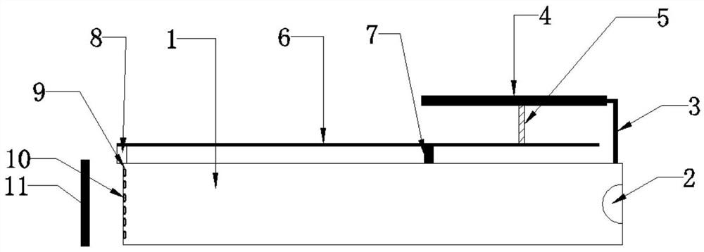
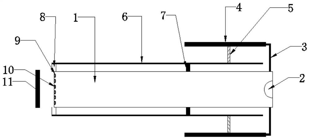
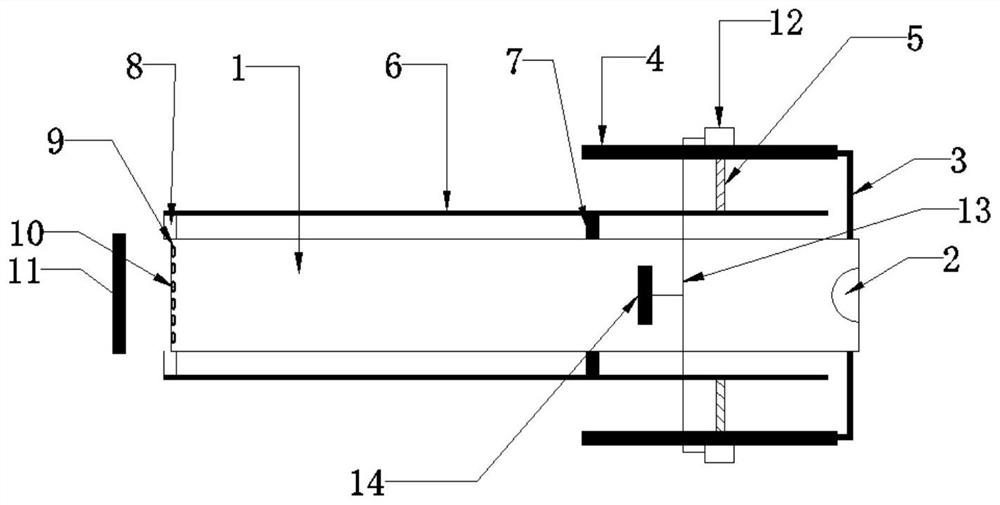
[0022] see figure 1 , a magnetic field intensity measuring device, comprising a cylindrical container 1, a light source 2 is arranged at one end of the cylindrical container 1, and a non-deformable material 4 is installed on the top and bottom of the cylindrical container 1 close to the light source 2 through a connecting arm 3, The non-deformable material 4 is provided with a giant magnetostrictive material rod 5 near the side of the cylindrical container 1, and the non-deformable material 4 is provided with a giant magnetostrictive material connecting portion 12, and the two giant magnetostrictive material connecting portions 12 are connected with a connection Rod 13, a handle 14 is provided at the middle position of the connecting rod 13, and a fulcrum 7 is provided at the top end of the cylindrical container 1 close to the connecting arm 3 and at the bottom end close to the connecting arm 3, and the fulcrum 7 is far away from the end of the cylindrical container 1 A light ...

Embodiment 2

[0025] see figure 1 , a magnetic field intensity measuring device, comprising a cylindrical container 1, a light source 2 is arranged at one end of the cylindrical container 1, and a non-deformable material 4 is installed on the top and bottom of the cylindrical container 1 close to the light source 2 through a connecting arm 3, The non-deformable material 4 is provided with a giant magnetostrictive material rod 5 near the side of the cylindrical container 1, and the non-deformable material 4 is provided with a giant magnetostrictive material connecting portion 12, and the two giant magnetostrictive material connecting portions 12 are connected with a connection Rod 13, a handle 14 is provided at the middle position of the connecting rod 13, and a fulcrum 7 is provided at the top end of the cylindrical container 1 close to the connecting arm 3 and at the bottom end close to the connecting arm 3, and the fulcrum 7 is far away from the end of the cylindrical container 1 A light ...

Embodiment 3

[0029] see figure 1 , a magnetic field intensity measuring device, comprising a cylindrical container 1, a light source 2 is arranged at one end of the cylindrical container 1, and a non-deformable material 4 is installed on the top and bottom of the cylindrical container 1 close to the light source 2 through a connecting arm 3, The non-deformable material 4 is provided with a giant magnetostrictive material rod 5 near the side of the cylindrical container 1, and the non-deformable material 4 is provided with a giant magnetostrictive material connecting portion 12, and the two giant magnetostrictive material connecting portions 12 are connected with a connection Rod 13, a handle 14 is provided at the middle position of the connecting rod 13, and a fulcrum 7 is provided at the top end of the cylindrical container 1 close to the connecting arm 3 and at the bottom end close to the connecting arm 3, and the fulcrum 7 is far away from the end of the cylindrical container 1 A light ...


PUM


Abstract

The invention belongs to the technical field of magnetic field intensity measuring devices, and particularly relates to a magnetic field intensity measuring device. The device comprises a cylindrical container, and a light source is arranged at one end in the cylindrical container. Non-deformable materials are mounted at the ends, close to the light source, of the top and the bottom of the cylindrical container through connecting arms. Giant magnetostrictive material rods are arranged on the sides, close to the cylindrical container, of the non-deformable materials, and giant magnetostrictive material connecting parts are arranged on the non-deformable materials. Fulcrums are arranged at the end, close to the connecting arm, of the top of the cylindrical container and the end, close to the connecting arm, of the bottom of the cylindrical container, and light levers are arranged at the ends, away from the cylindrical container, of the fulcrums. A light detector is arranged at the end, away from the light source, of the cylindrical container. The magnetic field causes the deformation of the giant magnetostrictive material to drive the light levers to stretch a graphene film, so that the space between the noble metal particles is changed, finally, the transmitted light is changed, the magnetic field intensity is obtained according to the change relation, and the device has the advantages of high sensitivity and high precision.

Description

technical field [0001] The invention relates to the technical field of magnetic field strength measuring devices, in particular to a magnetic field strength measuring device. Background technique [0002] The magnetic field strength tester adopts the popular single-chip microprocessor technology and high-resolution, high-linearity Hall-effect devices. It has the characteristics of advanced design, simple and convenient operation, high measurement accuracy and diversified functions. Surface field testing of magnetic devices. [0003] In the prior art, due to the limitation of the traditional structure, the detection sensitivity to the magnetic field strength is low, and the measurement accuracy is not high. Contents of the invention [0004] The object of the present invention is to provide a magnetic field intensity measuring device, which solves the problems of low measurement sensitivity and inaccurate measurement. [0005] In order to achieve the above object, the pre...

Claims


Application Information

Patent Timeline
IPC IPC(8): G01R33/032
CPCG01R33/0327
Inventor 不公告发明人
Owner 王计兰
Why Eureka
Try Eureka