MEMS flow sensor and preparation method thereof

A technology of flow sensor and heating resistance, which is applied in the direction of measuring flow/mass flow, liquid/fluid solid measurement, instruments, etc., which can solve the problem that the heat loss type flow sensor has a large temperature influence, the differential pressure type flow sensor is complicated to install and consumes a lot of power. and volume to improve measurement accuracy and sensitivity, suppress temperature drift, and reduce heat loss

Active Publication Date: 2021-07-27
EAST CHINA NORMAL UNIVERSITY
View PDF9 Cites 2 Cited by
  • Summary
  • Abstract
  • Description
  • Claims
  • Application Information

AI Technical Summary

Problems solved by technology

However, these flow sensors have their own advantages in different applications, and their shortcomings are also obvious
For example, volumetric, eddy current, and electromagnetic flow sensors usually exhibit large power consumption and volume; differential pressure flow sensors are more complicated to install, and heat loss flow sensors are greatly affected by external ambient temperature and have low accuracy; Type flow sensor has been widely studied because of its simple structure, no mechanical structure and easy integration, but in order to suppress the influence of temperature drift, it is usually necessary to add an additional temperature sensor near the flow sensor to measure the temperature of the base

Method used


Image

  • MEMS flow sensor and preparation method thereof
  • MEMS flow sensor and preparation method thereof
  • MEMS flow sensor and preparation method thereof

Examples


preparation example Construction

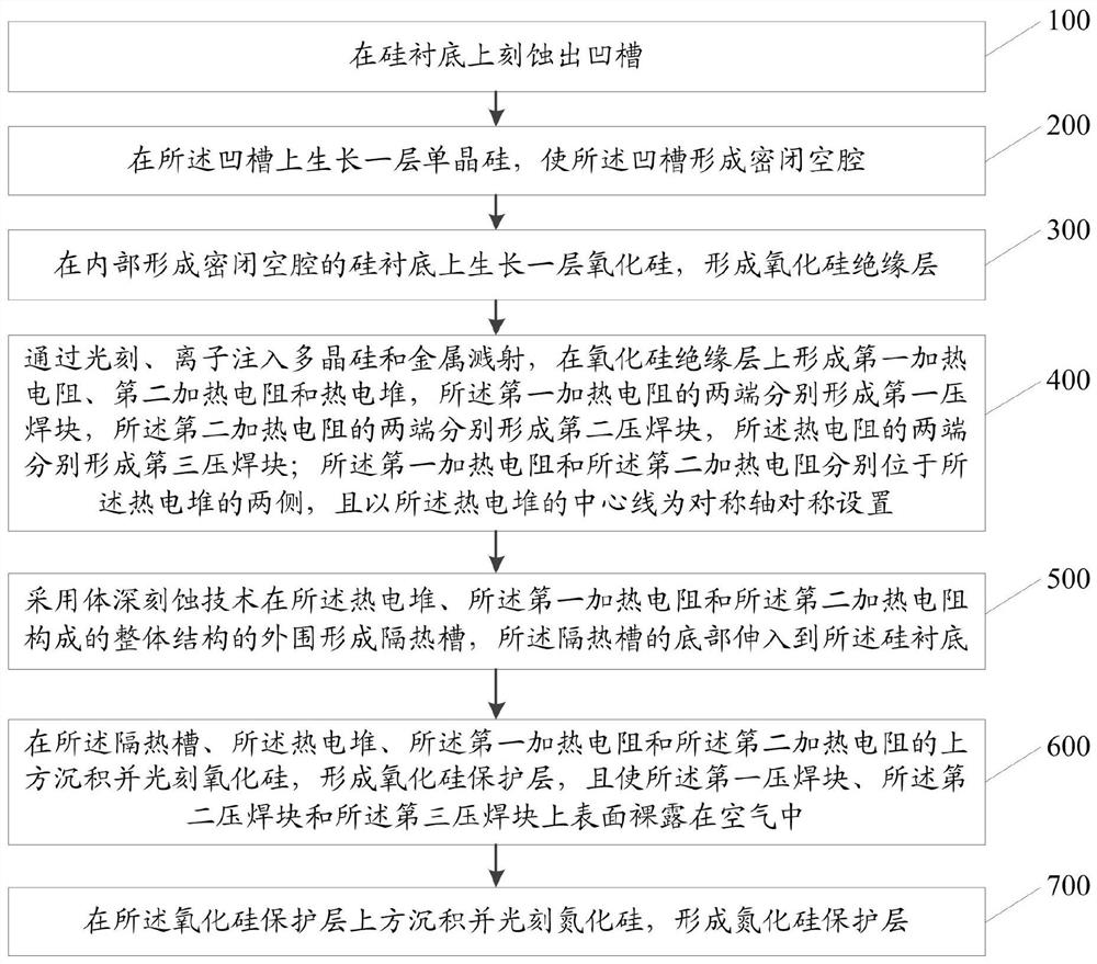
[0054] image 3 Be a kind of MEMS flow sensor preparation method flowchart of the present invention, as image 3 Shown, a kind of MEMS flow sensor preparation method comprises:

[0055] Step 100: Etching grooves on the silicon substrate.

[0056] Wherein, step 100 specifically includes:

[0057] Etching an initial groove on the silicon substrate by using an anisotropic reactive ion etching method;

[0058] Continue etching at the bottom of the initial groove by using an isotropic etching method to form the groove.

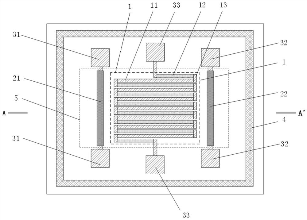
[0059] Optionally, the thermopile includes a plurality of thermocouples, each of the thermocouples is connected in series, the thermocouple includes a semiconductor arm and a metal arm, and one end of the semiconductor arm is connected to one end of the metal arm through a metal wire connection.

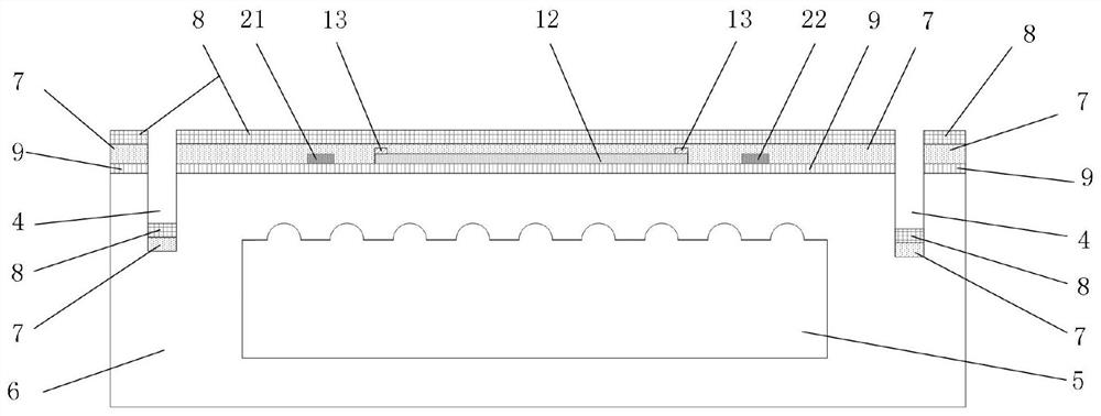
[0060] Step 200: growing a layer of single crystal silicon on the groove, so that the groove forms a closed cavity.

[0061] Step 300: growing a layer of silicon ox...


PUM


Abstract

The invention relates to an MEMS flow sensor and a preparation method thereof. A silicon substrate of the sensor is internally provided with a closed cavity, a silicon oxide insulating layer is laid on the silicon substrate, and a thermopile, a first heating resistor and a second heating resistor are arranged on the silicon oxide insulating layer; the first heating resistor and the second heating resistor are located on the two sides of the thermopile respectively and are symmetrically arranged with the center line of the thermopile as the symmetry axis, first pressure welding blocks are arranged at the two ends of the first heating resistor respectively, second pressure welding blocks are arranged at the two ends of the second heating resistor respectively, and third pressure welding blocks are arranged at the two ends of the thermopile respectively; the thermopile, the first heating resistor and the second heating resistor are covered with a silicon oxide insulating layer, and the silicon oxide insulating layer is covered with a silicon nitride protective layer; a heat insulation groove is formed in the periphery of an integral structure formed by the thermopile, the first heating resistor and the second heating resistor; a silicon oxide protection layer and a silicon nitride protection layer are sequentially laid on the groove bottom of the heat insulation groove. According to the invention, the measurement precision is improved.

Description

technical field [0001] The invention relates to the technical field of flow sensor preparation, in particular to a MEMS flow sensor and a preparation method. Background technique [0002] MEMS is an industrial technology that combines mechanical engineering and microelectronics technology, and its operating range is generally at the micro-nano level. MEMS technology is usually based on semiconductor materials, using processes such as surface micromachining, deep etching, and bulk micromachining, as well as related processes in the field of integrated circuits to prepare devices. [0003] Flow measurement is of great significance in industrial production and process control, such as consumer electronics, automotive and medical fields. There are many types of flow sensors commonly used at present, and with the help of MEMS technology, they have a wider development and application space. Common types of flow sensors on the market include: (1) Early flow sensors based on simpl...

Claims


Application Information

Patent Timeline
IPC IPC(8): G01F1/688G01F1/692
CPCG01F1/6888G01F1/692
Inventor 蔡春华毕恒昌吴幸王超伦
Owner EAST CHINA NORMAL UNIVERSITY
Why Eureka
Try Eureka