Method and device for cutting yarn on a textile machine

A textile machine and yarn technology, applied in the field of yarn cutting and installation on a textile machine, can solve problems such as excessive blade wear and tear, and achieve the effect of preventing side effects

Inactive Publication Date: 2005-07-20
USTER TECHNOLOGIES
View PDF0 Cites 0 Cited by
  • Summary
  • Abstract
  • Description
  • Claims
  • Application Information

AI Technical Summary

Problems solved by technology

[0004] A known shortcoming of this device can be seen from the fact that the cutting force of the blades is designed for the thickest yarn that the device is expected to handle, or that the drive always simply delivers its full force or output just right. sufficient power
The result in practice is that the blades wear out excessively or too quickly and the whole unit itself generates unnecessarily strong vibrations

Method used


Image

  • Method and device for cutting yarn on a textile machine
  • Method and device for cutting yarn on a textile machine
  • Method and device for cutting yarn on a textile machine

Examples


Embodiment Construction

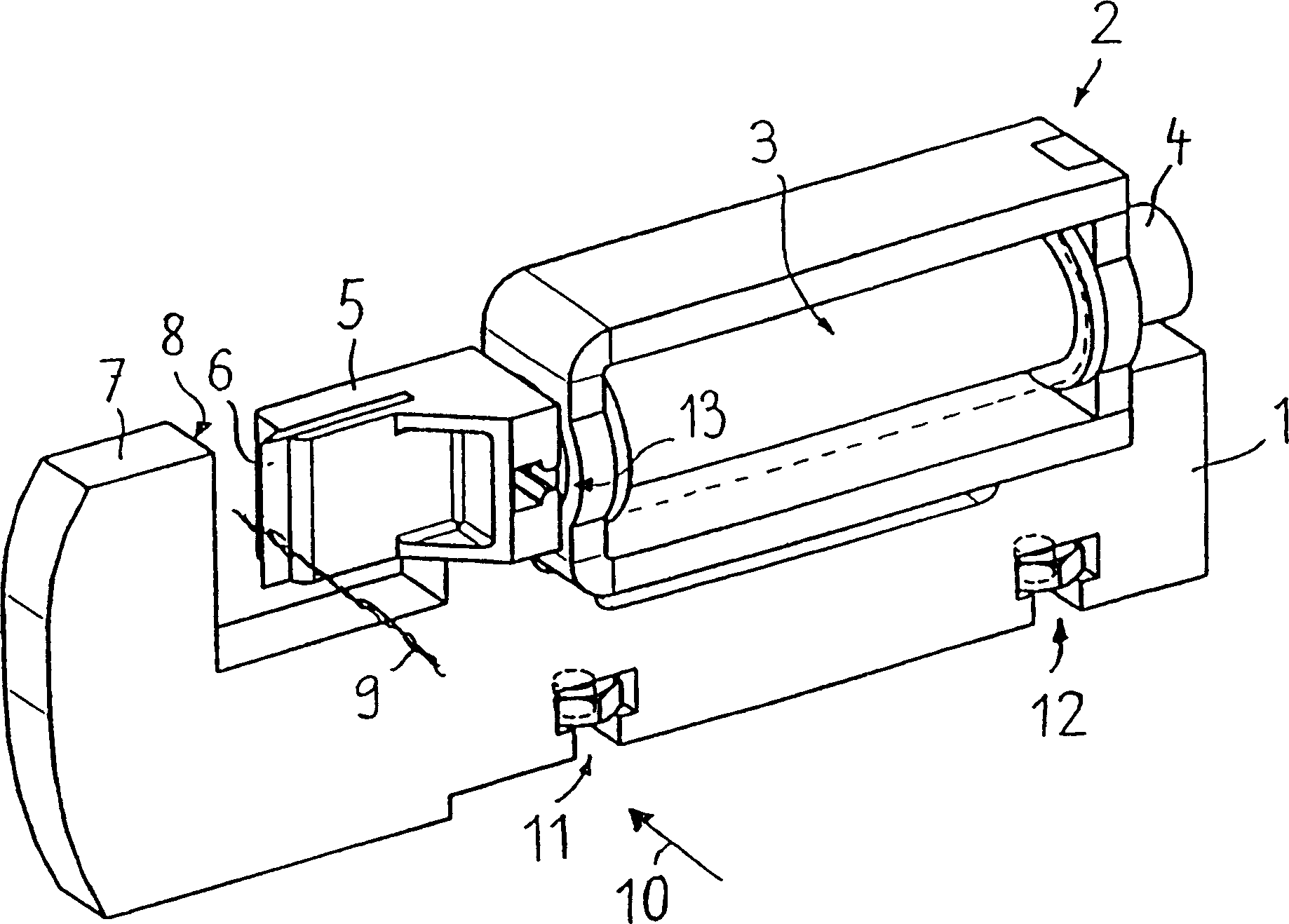
[0013] figure 1 The most important components of the display device, in particular a support 1, a plunger coil 2 with coil 3 and folding armature 4, which form a transmission mechanism for the knife holder 5 and for the blade 6, and a rear seat A frame or anvil 7 is part of the support 1 . The anvil 7 has a hardened surface 8 before which, for example, a thread 9 passes in the direction of the arrow 10 . On the support 1 can be seen the parts of the two screw connections 11 and 12, by means of which the yarn cutting device can be fixed on a textile machine. The blade 6 is preferably fixedly connected to the knife holder 5 and is connected to the plunger armature 4 by a releasable form-fit connection 13 on this side of the knife holder. This is known per se and need not be described in detail here, the coil 3 has figure 1 Windings not shown are connected to a control circuit.

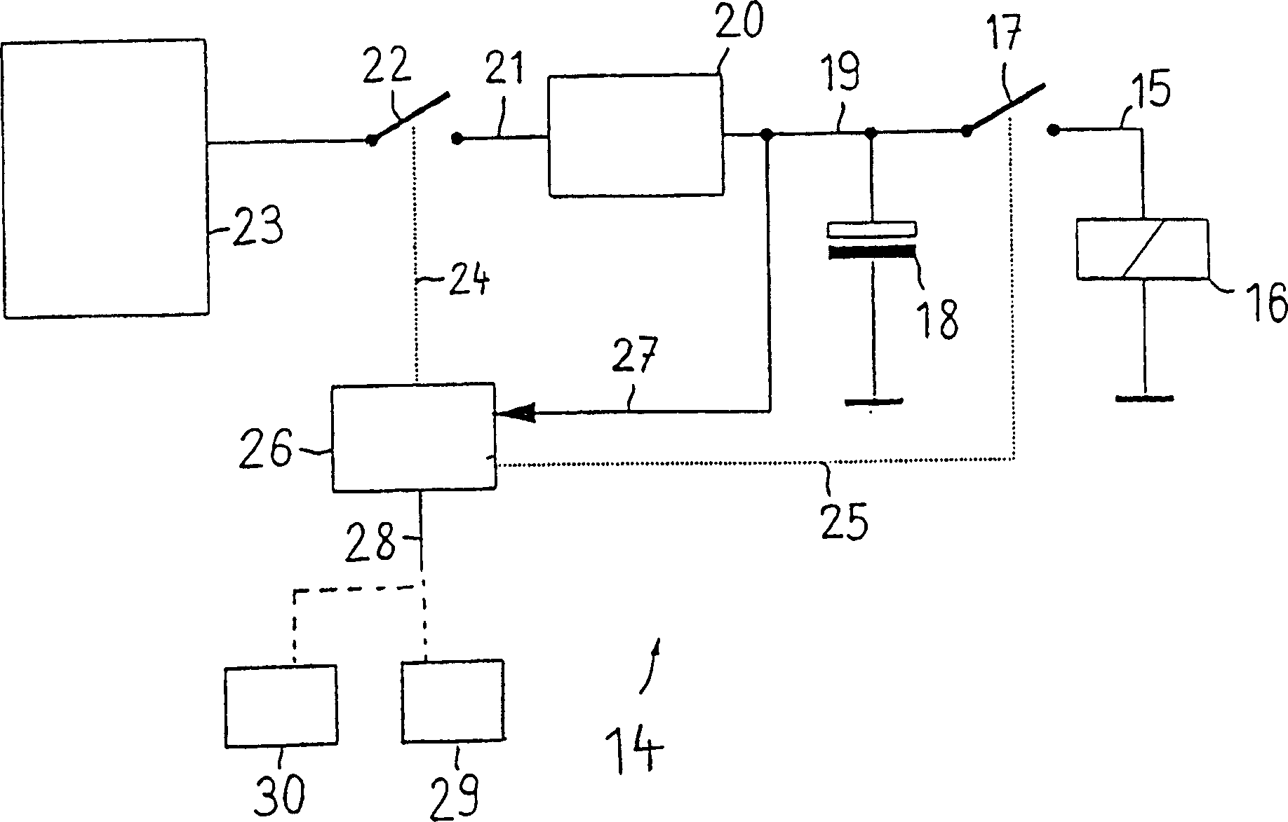
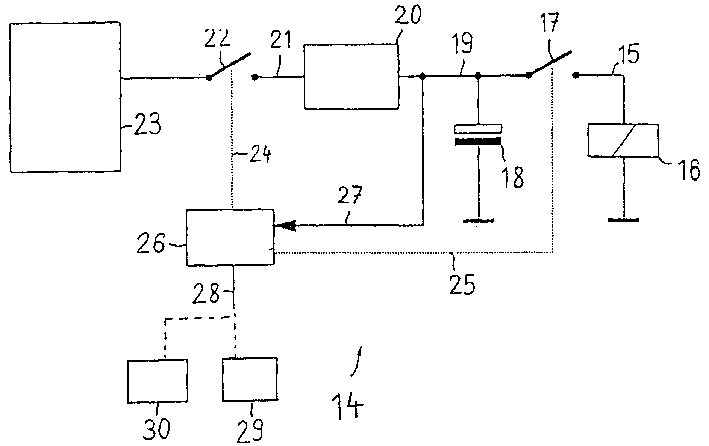
[0014] figure 2 A control circuit 14 is shown as a device for measuring the kinetic energy of t...


PUM


Abstract

A method and apparatus for cutting yarn (9) on a textile machine having a blade (6) which is supplied with kinetic energy via a drive (2, 3, 4). To be able to generate at all times a sufficient yet not excessive cutting power the kinetic energy is delivered in doses and rated in accordance with properties of the yarn and/or device. The drive thus comprises a device (14) for rating the kinetic energy of the blade.

Description

technical field [0001] The present invention relates to a method and device for cutting yarn with a blade on a textile machine, wherein the blade is powered by a transmission mechanism. Background technique [0002] Such devices are mainly placed on textile machines, such as winders. On this machine, these devices are used to remove yarn defects such as thick places or thin spots. The cutting method is to use a movably supported knife to cut a yarn when it is pressed against the rear seat bracket. For this purpose, the blade should sufficiently absorb the kinetic energy before it comes into contact with the yarn. Usually, the blade is accelerated to such a degree that its kinetic energy can quickly cut through all kinds of yarns. The remaining kinetic energy is dissipated on the rear seat bracket. Or the blade gets just enough energy for a given situation. The energy delivered to the blade can then fluctuate at will. [0003] On such devices as are known, the transmiss...

Claims


Application Information

Patent Timeline
Patent Type & Authority Patents(China)
IPC IPC(8): B65H54/71B65H63/06H01F7/16H01F7/18
CPCH01F7/1607B65H2701/31H01F7/1816B65H54/71B65H63/062
Inventor C·布赫
Owner USTER TECHNOLOGIES
Why Eureka
Try Eureka