Method for dynamically defining etch-recording speed of optical disk etch-recording machine

A recorder and speed technology, applied in optical recording/reproducing/erasing methods, recording/reproducing by optical methods, optical recording systems, etc., can solve the waste of discs, the failure of recording operations, and the lack of disc recording data. And other issues

Inactive Publication Date: 2005-08-17
LITE ON IT
View PDF0 Cites 0 Cited by
  • Summary
  • Abstract
  • Description
  • Claims
  • Application Information

AI Technical Summary

Problems solved by technology

[0004] Although the absolute groove time provides information such as the recording start point and the recording end point when the optical disc recorder performs data recording, it does not provide the recording speed (range) at which the optical disc will be able to record data correctly and completely. Relevant information that can be correctly read after the burn operation is completed
That is to say, when the optical disc recorder performs the data recording operation, it can only perform recording in accordance with the recording speed required by the user, which will easily lead to the failure of the entire recording operation and cause waste of the optical disc.
[0005] Therefore, it can be seen from the above that the above-mentioned general technology obviously has inconvenience and shortcoming in actual use, and needs to be improved.

Method used


Image

  • Method for dynamically defining etch-recording speed of optical disk etch-recording machine
  • Method for dynamically defining etch-recording speed of optical disk etch-recording machine
  • Method for dynamically defining etch-recording speed of optical disk etch-recording machine

Examples


Embodiment Construction

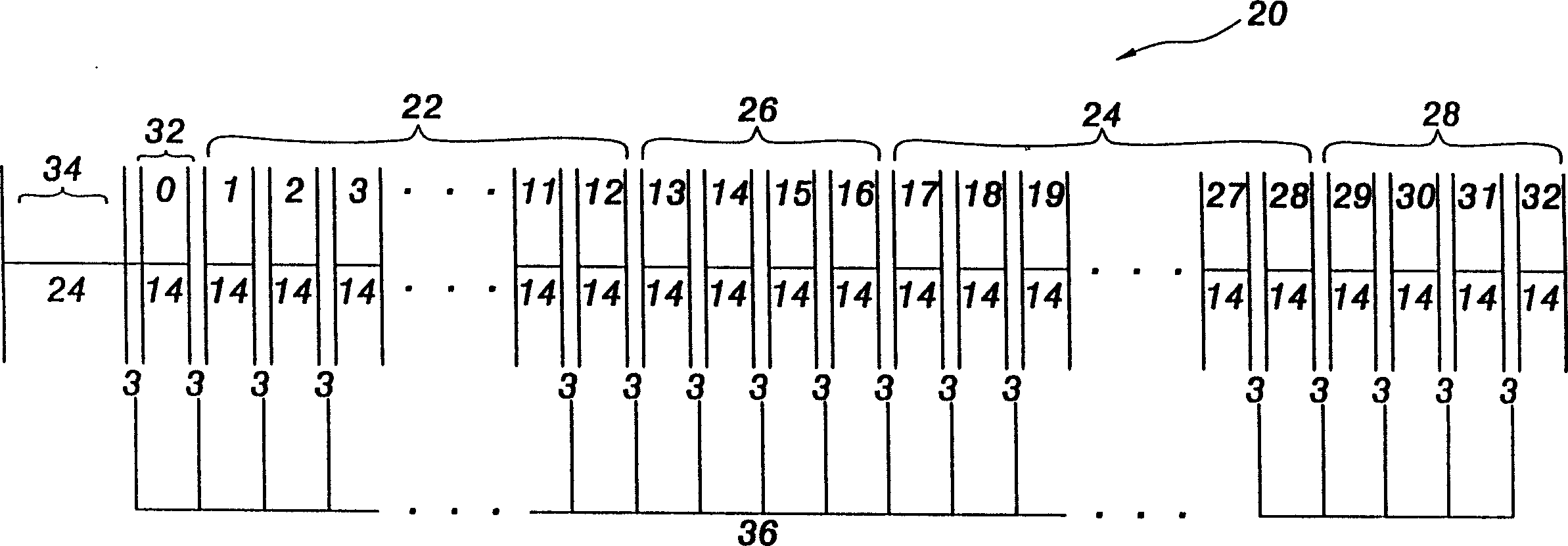
[0019] see figure 1 , figure 1 It is a schematic diagram of a data signal 20 written to an optical disc.

[0020] The data signal 20 takes an optical disc sound signal as an example, including two data bytes 22 and 24, a Q parity byte (Q parity) 26, a P parity byte (P parity) 28, sub A subcode 32 and a sync word 34 . Data bytes 22 and 24 respectively contain 12 bytes of digital data, Q parity byte 26 and P parity byte 28 contain 4 bytes of digital data respectively, and subcode byte 32 contains There is 1 byte of digital bit data. Add data bytes 22, 24, Q parity byte 26, P parity byte 28 and subcode byte 32 to obtain a data length equal to 33 bytes of digital bit data (0 in the icon) -32 sections). The aforementioned 33-byte digital bit data is subjected to an Eight-to-Fourteen Modulation (Eight-to-Fourteen Modulation, EFM) method to obtain a 462-bit Eight-to-Fourteen Modulation code (EFM code). Synchronization block 34 does not need to undergo eight-to-fourteen modulati...


PUM


Abstract

The dynamic determination method of etching speed of optical disk etching machine includes the following steps: presetting at least an error admissible upper limit in every presetting time, calcualting a data error rate when the optical disk etching amchine is operated in a presetting time at a correspondent etching speed and comparing error admissible upper limit with data error rate, when the data error rate is less than error admissible upper limit, said etching speed can be switched to higher etching speed, if the data error rate is greater than the admissible upper limit, said optical disk etching machine can be continuously operated at said speed.

Description

technical field [0001] The invention provides a method for dynamically determining the recording speed of an optical disc recorder, especially a method for dynamically adjusting the recording speed according to the data error rate of the recording object. Background technique [0002] At present, the recording speed of CD-R recorders on the market has reached 24 times, and the continuous improvement of recording speed is a foreseeable development trend. However, the characteristics of optical discs produced by different optical disc manufacturers are not exactly the same, and the data recording conditions at the same recording speed are also different. At a certain data recording speed, it may happen that a certain brand of discs can completely and correctly perform data recording, while another brand of discs may have data recording loss, or the recording is complete but cannot be read. Take unexpected situations. [0003] When the optical disk is manufactured and leaves ...

Claims


Application Information

Patent Timeline
Patent Type & Authority Patents(China)
IPC IPC(8): G11B7/0037G11B7/0045G11B7/006
Inventor 汪益适张永裕
Owner LITE ON IT
Why Eureka
Try Eureka