

Developing device and image forming device installed with the developing device
A developing device and a developer technology, which are applied in the fields of electric recording technology using charge patterns, equipment for electric recording technology using charge patterns, and electrography, etc., which can solve the problem of different toner intake and unstable toner concentration , uneven image density, etc.
- Summary
- Abstract
- Description
- Claims
- Application Information
AI Technical Summary
Problems solved by technology
Method used
Image

Examples
no. 1 example
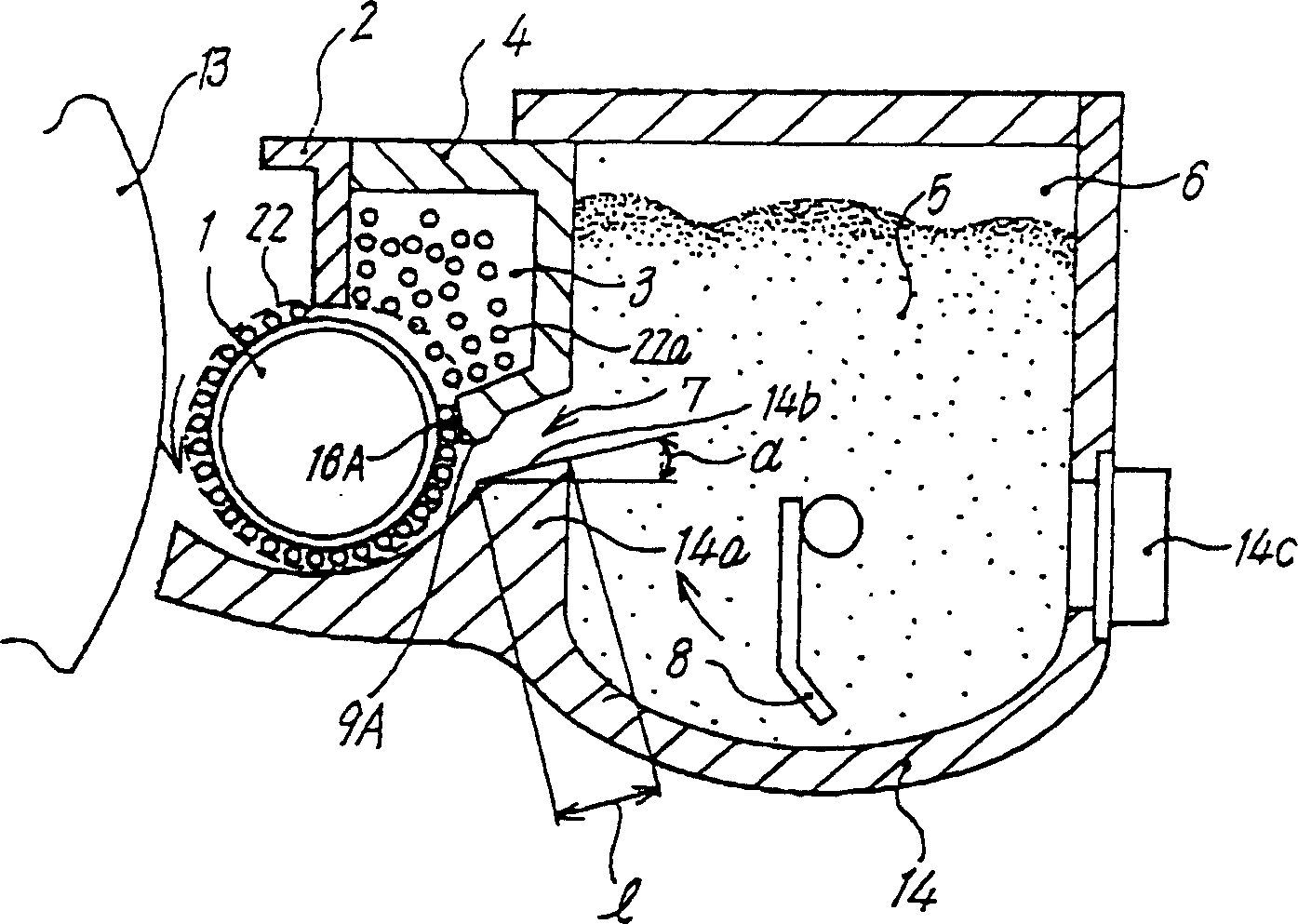
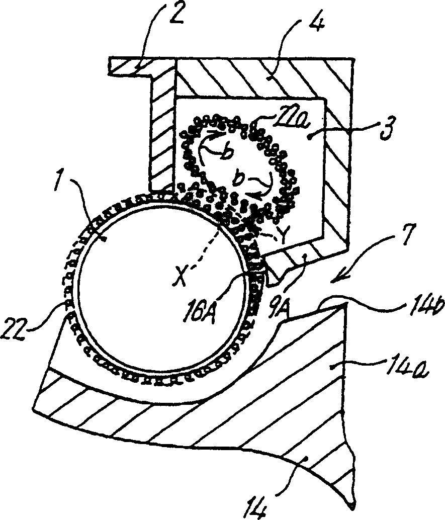
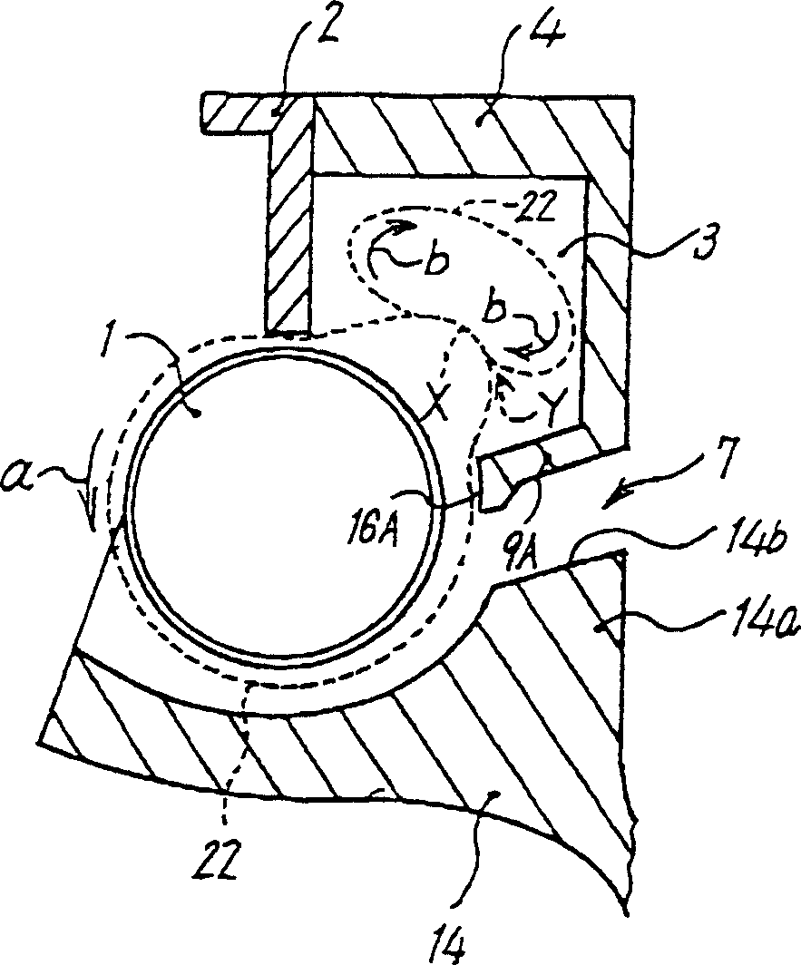
[0082] figure 1 is a schematic configuration diagram of the developing device according to the first embodiment of the present invention, in figure 1Among them, the developing device is arranged on the side of the photoreceptor drum 13 as a latent image carrier, and it is composed of a developing sleeve 1 as a developer carrier, a developer housing case 4, a first restricting member 2, and a second restricting member. 9A, the toner hopper 6 as the toner storage part, the developing case 14, and the like are constituted.
[0083] The developing sleeve 1 is driven to rotate in the direction of the arrow shown in the drawing by an unillustrated driving device, and a developer 22 composed of toner and magnetic particles (carriers) is placed on the surface of the developing sleeve 1 . The developing sleeve 1 is made of a non-magnetic material, and a magnet (not shown) as a magnetic field generator is provided therein.
[0084] The first restricting member 2 is used to restrict ...
no. 2 example
[0103] 5 is a schematic configuration diagram of a developing device according to a second embodiment of the present invention. The basic structure and operation of the developing device in FIG. Characteristic part of this embodiment.
[0104] FIG. 6 is an enlarged view of the vicinity of the second restricting member 9B of the developing device shown in FIG. 5 . In this embodiment, the shape of the second restricting member 9B is set so that the frictional force is increased to sufficiently charge the toner 5 . Specifically, as shown in FIG. 6, in the opposite surface 16B of the second restricting member 9B to the developing sleeve 1, the gap Ga is larger than the gap Gb. 1, the gap Gb is the gap between the downstream end and the surface of the developing sleeve 1.
[0105] In the above structure, the developer layer 22 including the toner 5 placed on the developing sleeve 1 is restricted by the second restricting member 9B, and the restricted developer 22 forms the develo...
no. 3 example
[0114] Figure 9 is a schematic configuration diagram of a developing device according to a third embodiment of the present invention. In the developing device of this embodiment, the toner replenishing passage is constituted by the developer housing case 4 at the portion forming the second restricting member 9c and the developing housing 14 at the position opposite to the developer housing case 4. When the toner concentration (weight percentage of the toner in the developer) is within an appropriate range, the developer is retained in the toner supply channel 7 to form the developer retention portion 10 . On the downstream side of the developer accumulation portion 10 of the toner supply passage 7, a developer circulation portion 11 is formed by the second restricting member 9c and the development casing 14, and the developer is circulated. Figure 9 The parts of the developing device shown that are substantially the same as those in the above-mentioned embodiment 1 are mark...
PUM
 Abstract
Description
Claims
Application Information